
Steering in circles
**** Disclaimer: Do as I say, not what I do. Do not attempt to copy the procedures you’ll see in this post. Experimenting with the steering in your car can be dangerous.****
Not working from the same basic materials as Waid 302, I was not able to follow many of the same methods he used. One of his ideas, I could use.
I wanted the steering column to look as natural as possible so this means using as much of the existing visible Mustang parts as possible.
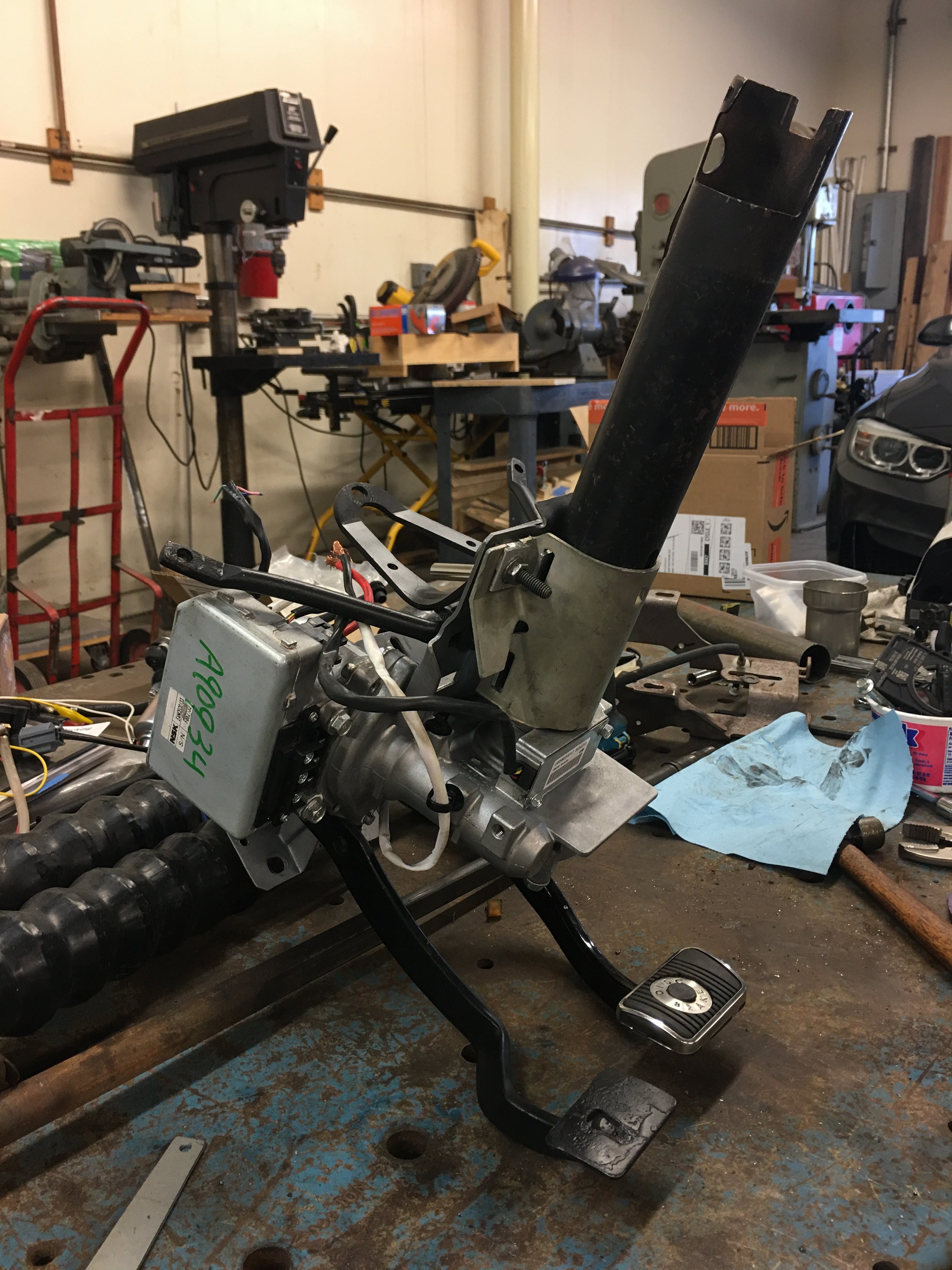
The steering column is held in place by a two piece bracket that wraps around the column and then bolts to the pedal assembly mounting plate. This two piece bracket and the column are keyed to each other which keeps the column from rotating.


It just so happen that the only place large enough to house the EPAS is just past this two piece bracket so that’s where I started and cut the outer column tube. The tube, bracket and EPAS were mounted onto the pedal assembly to verify the fit.
Here is the one similarity between Waid 302 and this fabrication job.


The EPAS shaft tube base is 1 13/16” and the inside diameter of the steering column outer tube is 2 1/16”. Unattended, that could cause some sloppy centering of the two shafts.
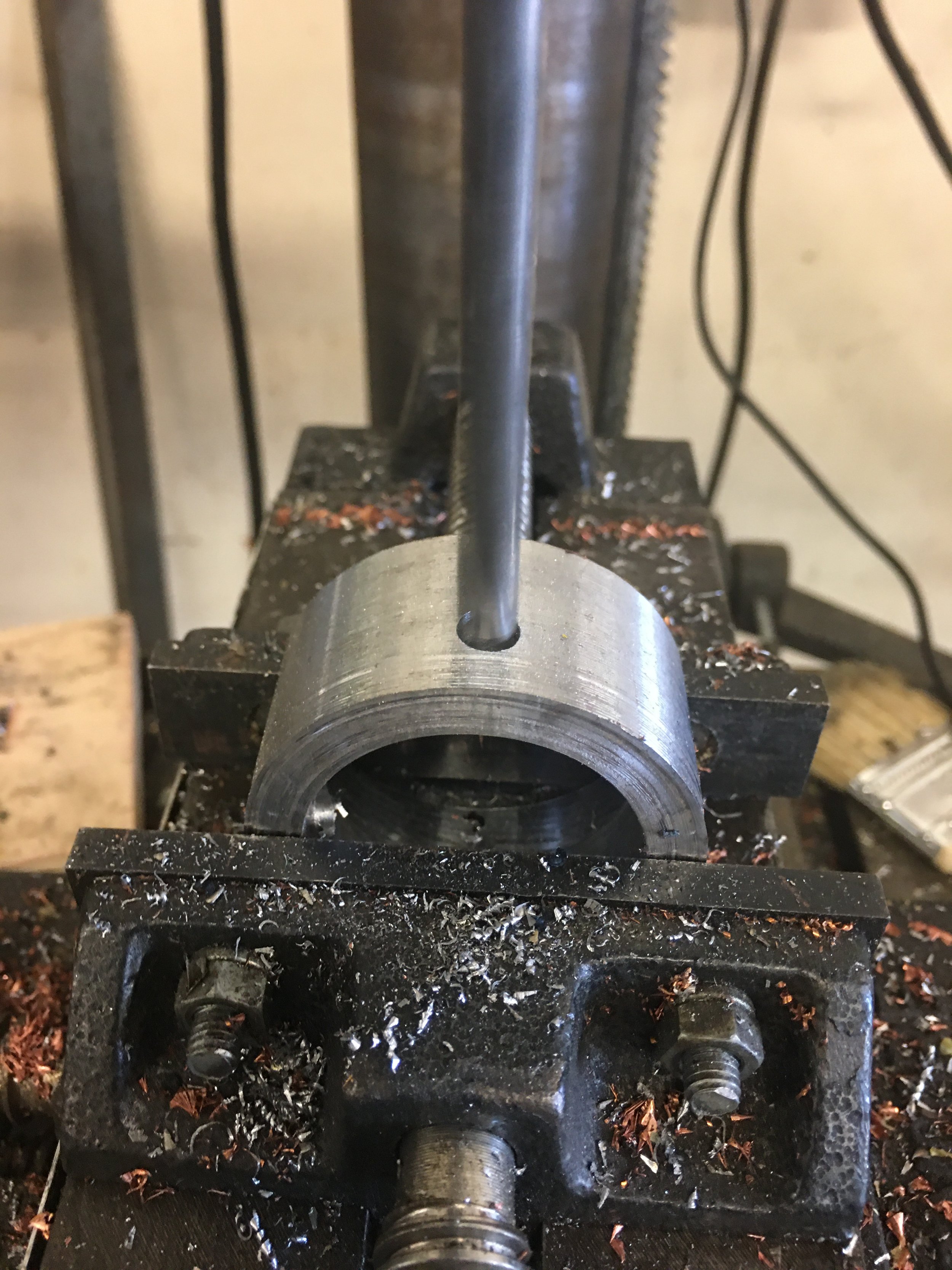
I machined out a spacer to bridge the gap and also act as a mount for the outer shaft to anchor to.


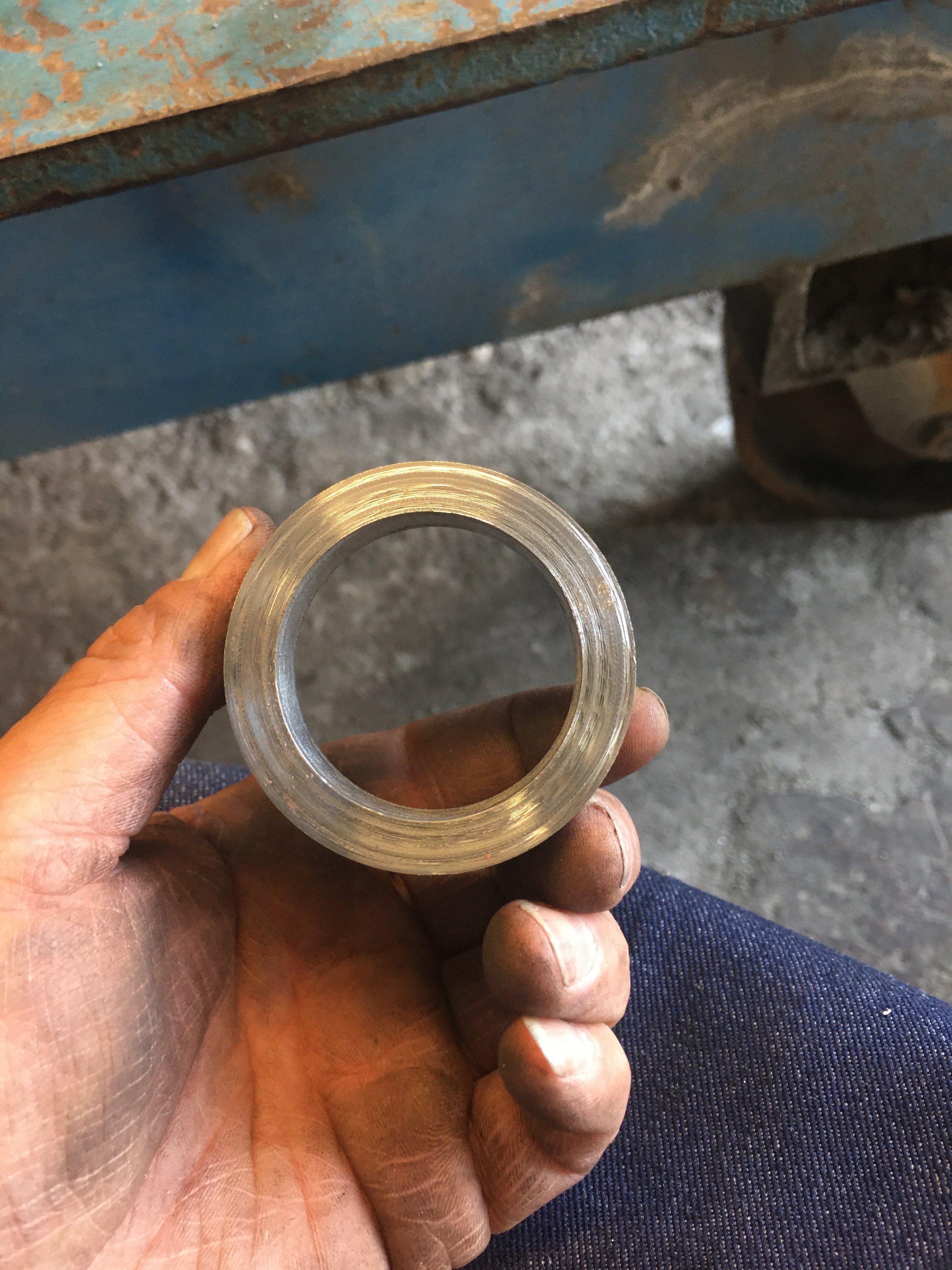

Obviously I am not a machinist but when I can make something even as simple as this collar, I surprise myself. It’s ugly but as long as it does what I made it for, it will never be seen outside of these pictures.
As usual, a test fit of the collar. It fit well so it was on to making some holes so the collar can be plug welded to the EPAS steel sleeve.


With the collar welded to the EPAS shaft base, I can test fit the outer sleeve once more to make sure the heat from the weld didn’t warp the ring.


This is as far as the Waid build and my build are similar. After this it’s all my own trial and error experiments.
The Rogue has a two piece steering column. I don’t know why they’re called officially so I’ll refer to them as the lower column and the upper column. With the lower column set up with the spacer/collar, it’s a good time to do some work on the upper column.
When I started on this project, the idea was to use the lower column and use some sort of Borgeson coupler to graft the Mustangs steering shaft to the Rogue shaft. One day I’m doing my usual staring at the parts waiting for inspiration and I think I got it.
I’m looking at the end of the steering shaft in the upper column. Unlike the Mustang that uses a nut to hold the steering wheel to the shaft, the Rogue uses a bolt. The end of the Rogue steering shaft is drilled and tapped for a 12 or 14 mm bolt.

Before I can pursue this line of thinking further, I have to see if the upper column will fit inside of the Mustang steering column outer tube. To be honest, I know it won’t fit. It’s just a matter of making it fit.

The most obvious obstruction are the lock tabs. This upper column is the adjustable part that makes this a telescoping column. The tabs are part of the friction lock.
These get cut off with the band saw and it wasn’t enough. Instead of cutting a little here and a little there, it gets chucked into the lathe.


I turned down the upper column a little too much. There were no negatives to this and I know that have all of the clearance that I need.
Now let’s see about getting that Mustang steering shaft to graft to the Nissan.