
Rogue-stang EPAS steering column #5
****Disclaimer: Please do not try any of this stuff you’re reading in this section. If you decide to use this information to create your own electric power steering, you do so of your own volition. Altering your steering could result in failure of the system and endanger your safety and maybe your life****
The steering column, as mounted, rocks up and down. The fulcrum is the single mounting point where the steering column bracket is bolted to the pedal assembly mount. I don’t think the bracket at the back of the EPAS is going to be enough.
Before I come up with a way to make the column more solid, I should see if I can connect this new column to the Mustang steering box.
Let me explain the Disclaimer for the steering column build. The stock steering column of the Mustang is designed to collapse in on itself under certain accident conditions. With the modifications I performed, I have completely defeated this feature. It’s perfect. I’m driving along and I have to panic stop. My modified brake booster fails and I slam, head on, into the back of a big rig and I’m impaled, right through the chest, by my rigid steering column becoming a human shish kebab. Ahhh, such warm fuzzy thoughts.
On with the show!
The thought had been to use a Borgeson coupler to adapt the Mustangs lower steering shaft to the Nissan EPAS. When I started investigating this, I discovered that Borgeson does not have a coupler with a matching spline count as what the Rogue uses. I do have that output shaft that came with the EPAS system. maybe the slip joint can be cut off and welded to the Mustang steering shaft.
With the Rogues-tang steering column on the bench along with the jointed Nissan output shaft. I’m playing with the output shaft and it dawns on me that this thing telescopes. I knew that but I didn’t think about it till now. There’s only about four inches of travel but it does collapse. With my twisted sort of rationalizing logic, by using this shaft in it’s entirety, aren’t I restoring some of the safety feature I had cut out of the steering column?
I can now move forward.
Put the Rogue-stang column back into the car and slide the output shaft into place. I want to know if the shaft will reach all the way to the steering box and if it’s a straight shot or is there an angle to it.
The shaft reaches the steering box rag joint and then some. There’s another U-joint, slip fit coupler on the steering gear side that will have to come off but even then, it still has more than enough reach to hit the rag joint.
I have an idea. The Mustang steering shaft is mostly hollow, with the second U-joint removed from the collapsable output shaft, the cut end should be able to fit inside the Mustangs steering shaft.


Six inches are removed from the steering box end of the steering shaft and it does, in fact, slide right over the amputated end of the Nissan shaft but the fit is way loose. I think I need a shim.


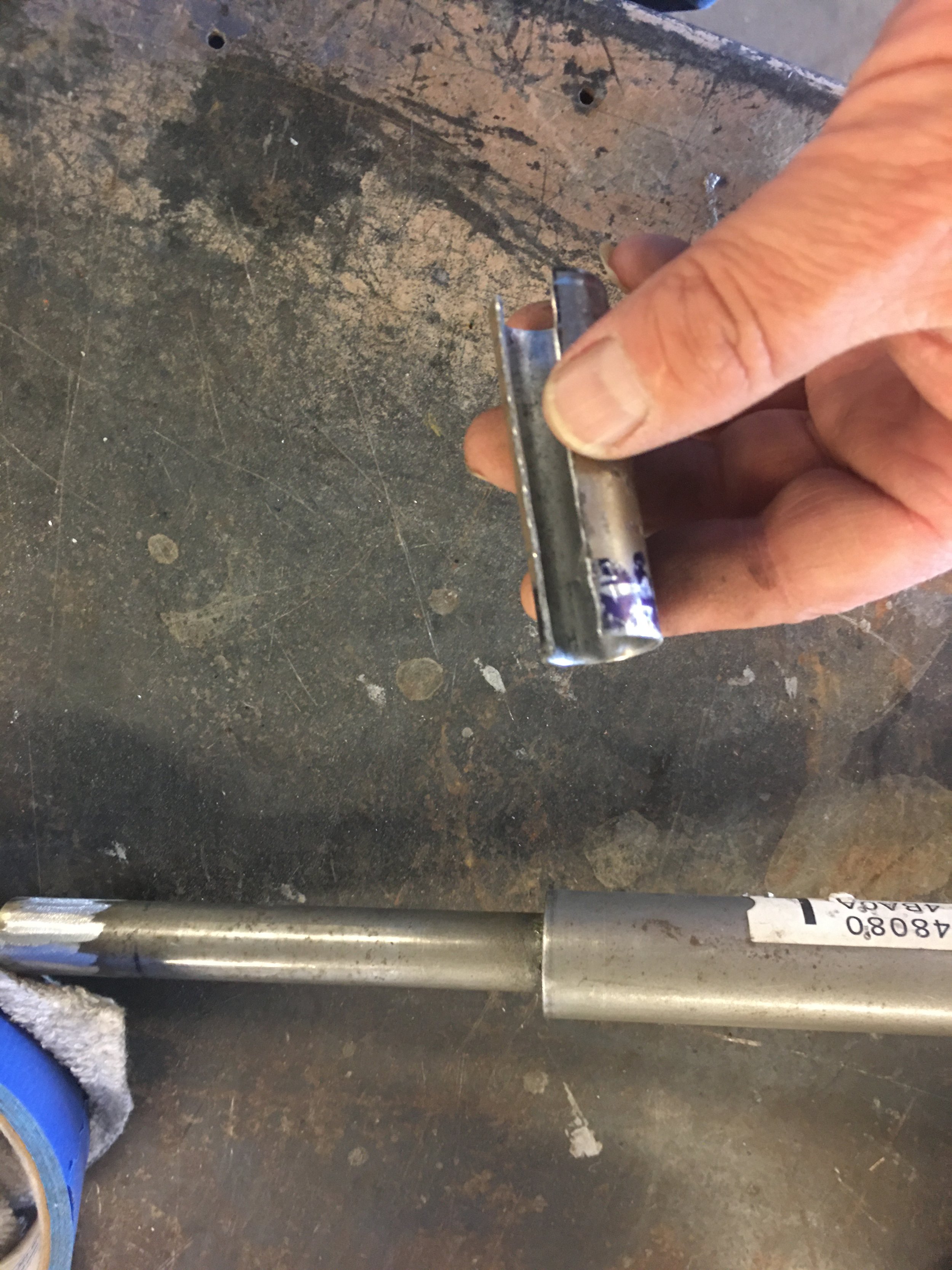
The vernier caliper says there is around ,080-something of an inch difference between the OD of the Nissan part and the ID of the Mustangs. It’s not imperative but it is important to me that I keep the Nissan shaft concentric to the Mustang flange.
I have no metal sleeves at the shop. Half of the gap is .040” which is the thickness of 18 gauge metal. I have that. I’ll make my own sleeve.


I have a 5/8” bar stock to use as a form. The use of the bar stock, a bench vise and a hammer gets the shaping of the sleeve under way. With the sleeve rough formed, the extra metal is cut away so they don’t overlap during the final shaping.


I use the hammer to form the ends around the Nissan shaft to get the sleeve to fit as tight as possible around it.

Toes crossed, my fingers are busy, the sleeve wrapped Nissan shaft is guided into the Mustang flange. It fits! Kinda.

It is very much an interference fit so the flange is driven onto the shaft until none of the sleeve is exposed.

That’s right, Test fit!
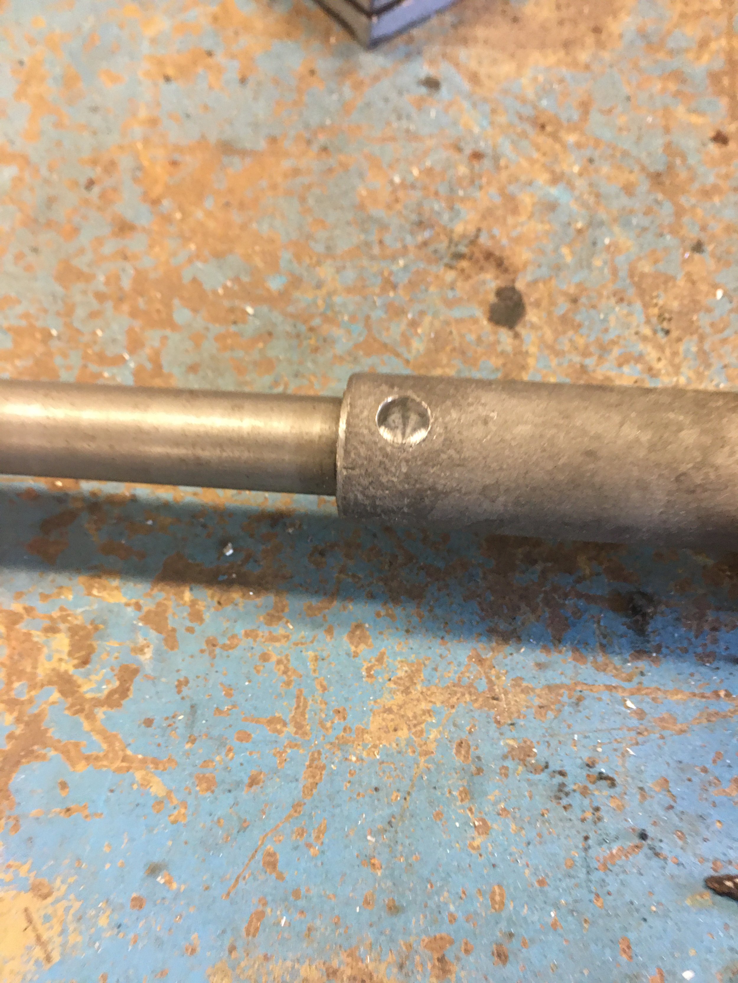
With the output shaft connected to it, the Rogue-stang column is bolted back into the car and the output shaft is snaked through the firewall opening and the flange is bolted to the rag joint of the steering box.


Everything goes to where it’s supposed to but the output shaft is sitting low through the firewall opening. It should sit more in the center. Earlier fittings of the Rogue-stang column was without the motor being attached and the shaft sat closer to center. With this last fitting, the motor was installed onto the EPAS.
When the EPAS was positioned in the car, the motor could be rotated around the center of the column shaft within a 270 degree arc, maybe a little smaller, but I wanted the motor at the 12 O’clock position to keep it out of view. The EPAS control box extends past the motor so that was removed to be relocated to a different location. What I didn’t notice is that the motor is hitting the bottom of the lower cowl causing the back of the EPAS to angle downward. Luckily the other side of the lower cowl is open, it’s an open valley.
I grab the acetylene torch and a large ball-peen hammer and beat the hell out of the metal. The metal is heated till it glows orange and then beat upwards until the metal cools. The process is repeated until the motor no longer touches any part of the lower cowl. This takes a while as the Rogue-stang column has to be removed to heat and beat the metal and then reinstalled to check for clearance.


Eventually I achieve my goal and now the output shaft sits much closer to center of the firewall opening.
Now that the pieces fit together, the output shaft is removed and the two parts are drilled and plug welded together.


To use an electronics term, we now have connectivity and I have an idea now of how to stabilize the Rogue-stang column.