
Column #6
What better way to stabilize the steering column than to go the same route as the factory.
With the upper section done, there was a pile of scraps sitting on the work bench.

Why do I have three lowers? I should only have two. Getting old sucks.
I start experimenting with the lower section of the Mustangs steering column. This section is part of the collapsible structure. Even though it doesn’t look it, this section is still pretty stiff. The first thing to find out is if the Rogue output shaft will fit through the center of this perforated tube.


You’ll notice the difference between the first picture at the top and the ones just above. Besides being cleaner and having a new firewall seal on the mount, the added pipe is bigger. The top picture with the 2 1/2”? tube was just a little too small for the swivel end to move freely when the joint was connected to the output of the EPAS. Replacing the 2 1/2” pipe with a 3” diameter piece fixed that issue. Of course the initial question was answered. Yes, the Nissan output shaft will fit easily through the Mustang lower shell.
The next puzzle to solve was how to get the Mustang lower to attach to the EPAS housing.
The Rogue EPAS was designed with a mount cast into the rear cover of the output section of the EPAS.

I later regretted it but the first thing I did was remove the cover and cut the mount off. I regretted this move later on when I was trying to figure out a way to secure the back of the EPAS to keep the Rogue-stang column from rocking. Ironic. I think in the end, it all worked out better.


By removing the mount, I learned that the cover will come off and I was able to check out the inside of the housing. Nothing critical around the edges.
From the two pictures at the top, you can see that I had added a lip or ring to the mouth of the 3” pipe. This is the mounting ring for the lower column to attach to the Rogue unit.
That back cover was removed once again to machine the surface a little flatter.
It’s not pretty but the cover is more level.

Both the cover and the mounting ring were drilled around their circumference.
I don’t remember how but I could only guess that ring had been welded to the 3” pipe before they were attached to the lower column piece. I would imagine the pipe and ring would have been clamped in place on the cover while it was not on the EPAS. Once everything was centered to my liking, I would think the pieces were drilled all at one time. I don’t have pictures of my doing that but here’s something just to have something.
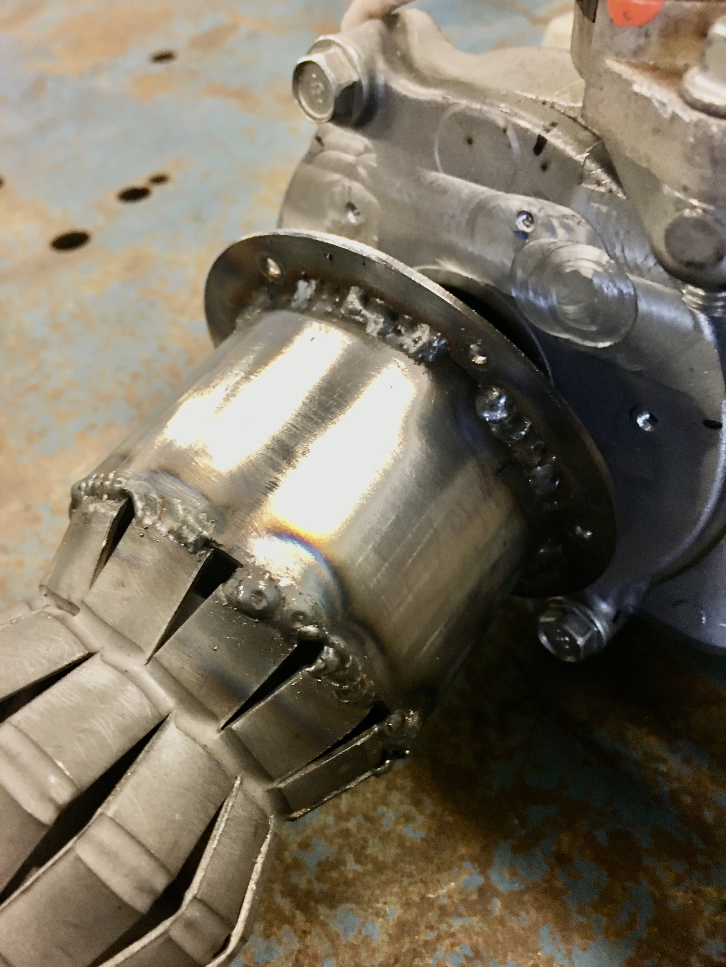
Yes, the welds are ugly but they work. I have gotten better since I did these a couple of years ago.
The ring is attached to the cover using self tapping screws

It’s time for full assembly and another test fit.


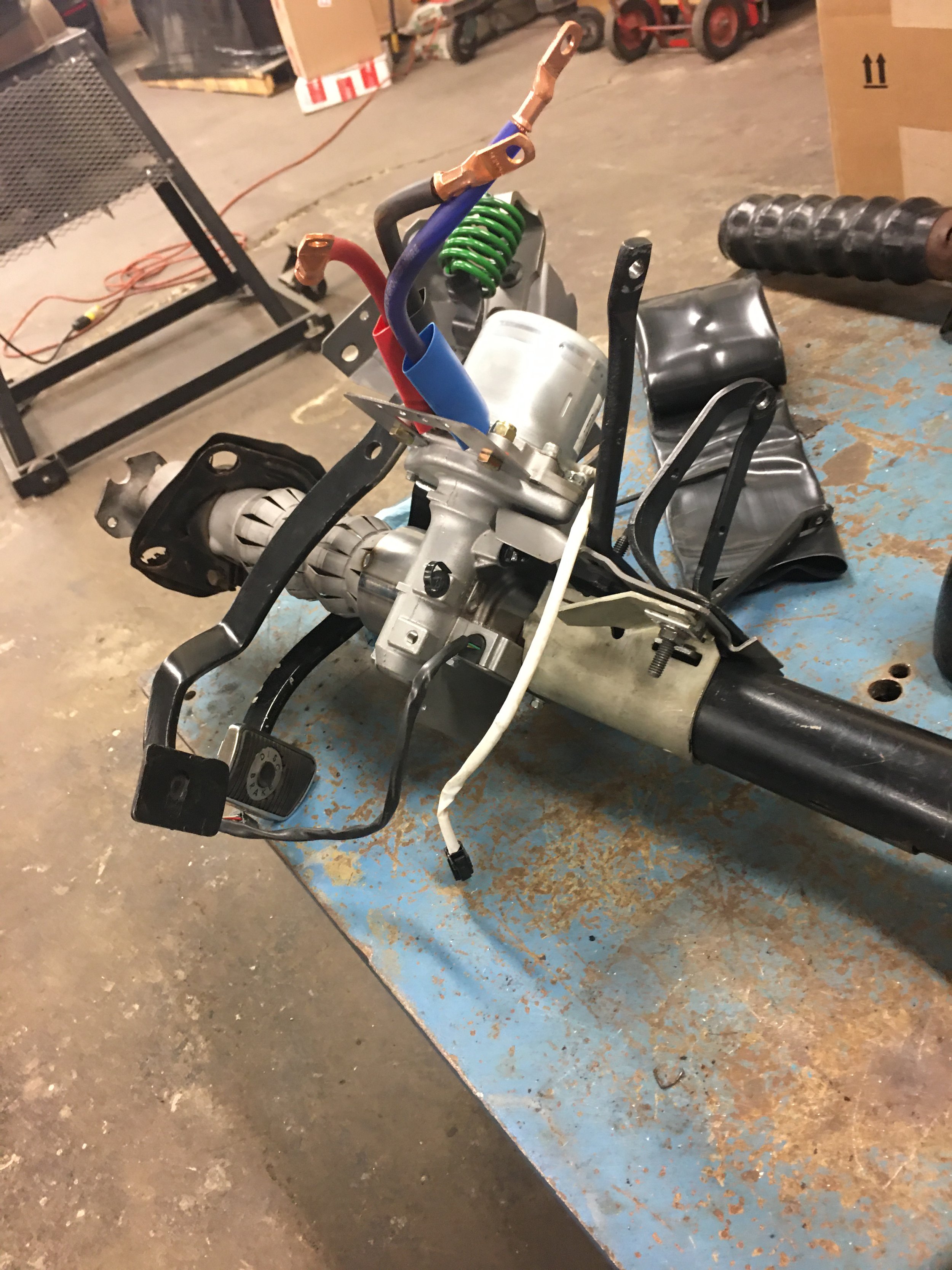

The EPAS was wired to use the EPS control in a remote location. It’s supposed to be attached directly to the EPAS but it wouldn’t fit. The size wires might be a bit overkill but I’d rather have too large a cable than have the restriction of too small and possibly fry the wires. The EPS control was mounted on the left kick panel.

Using the lower column as a way to secure the Rogue-stang column worked great. The column was as solid as stock. Even better was that I was able to turn the wheels without anything hanging up. Without all of the weight from body panels and bunch of other things being on the car, the steering turned without a lot of effort and the system wasn’t even powered.
I had swapped out the original gear box with a rebuilt 16:1 box so I was expecting to have to use more effort. Again, the car isn’t completely built which means the front end is a lot lighter than it will be so it’s not a legit test. Either way, the steering system does work.
The column was removed again, hopefully for the final time, to disassemble the unit, paint up the bare metal and get a cover on the lower column. All aesthetics but after all the time and work, it should look nice.
The lower column was painted black to match the rest of the metal parts. I didn’t touch the EPAS section, I’ll leave that natural aluminum.
The stock lower column has a rubber/plastic cover over it. I don’t know what Ford used but I found some 3 1/2” heat shrink. It’s unusual, it’s shiny. I’m used to a dull heat shrink. The fit was tight, in fact, I had to stretch it out a little to get it to slip over the undulating surface of the tube. I won the fight and used a heat gun to shrink the cover and it formed pretty well to the pipe.

With that finished I reassembled the lower section, fed the output shaft through the lower column and then bolted everything together.


If this thing turns out to be a failure and it doesn’t kill me, I’m hanging it on the wall, it looks pretty awesome.