Push Rod, that lazy bastard.
***This post focuses on heavily modifying the power brake vacuum booster. DO NOT ATTEMPT ANY OF THESE MODIFICATIONS. This is to be read for entertainment only. Tampering with the factory structure could lead to brake failure and can endanger your life and those around you.***
Earlier, when the wedge was bolted to the firewall, I noticed that there might be a clearance issue with the vacuum booster push rod.
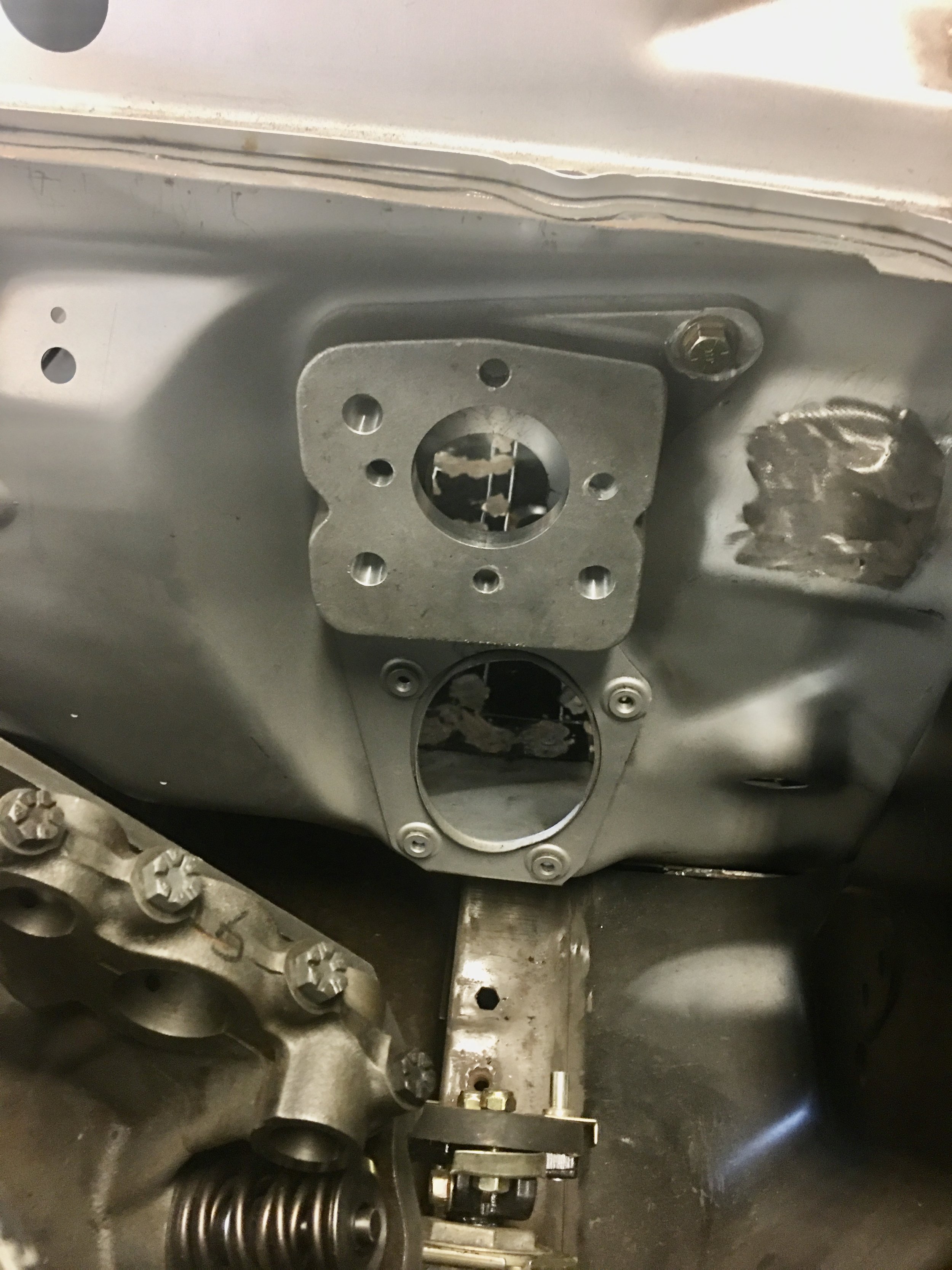
If you look in the center of the wedge, you can see how much higher the booster and master cylinder are relocated. You can also see that the access hole through the firewall needs to be raised.
A paper template gives a better idea of how much the hole needs to move.
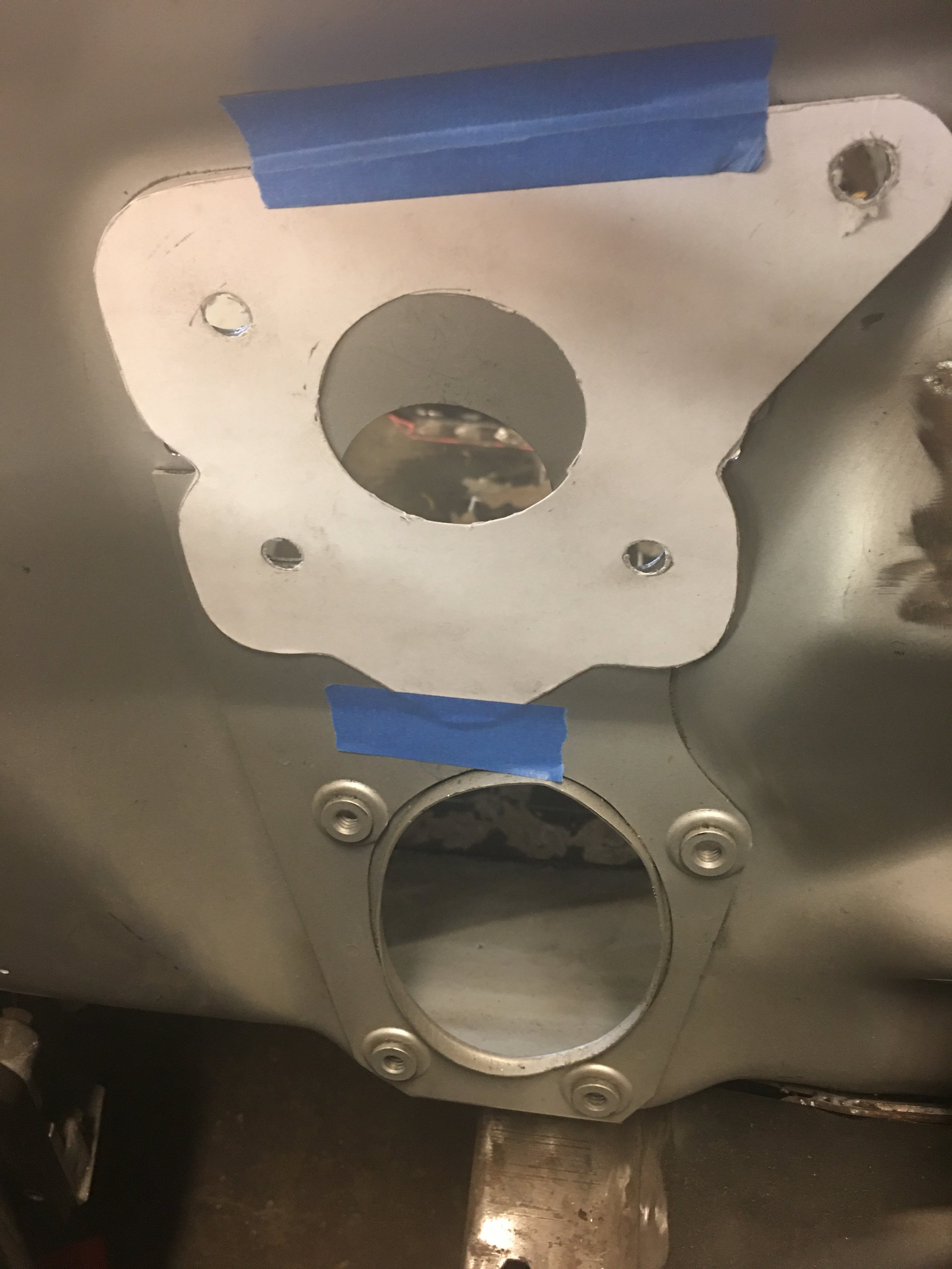


Because it’s what I want to do, The existing hole is sealed shut with a patch. When the new hole is cut, I want a nice clean, round opening…


Except I forgot to take into account the angle of the wedge when I traced the paper pattern from it. I didn’t compensate for the angle so the hole in the template is a little high. I didn’t see this until the hole was cut and the wedge held in place. The die grinder made the necessary adjustment.

In order to get a good measurement of the push rod, the pedal assembly is bolted to the firewall along with the vacuum booster and Boss wedge.
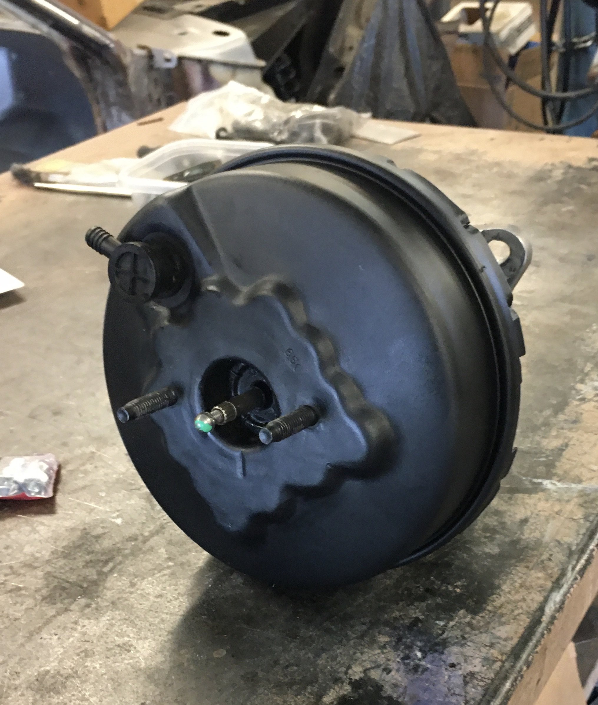
A modified booster is reassembled complete with over long push rod.
Bolting everything to the car, the push rod is slightly deflected by the fixed pin on the brake pedal arm that the booster push rod attacks to.
The push rod is marked with a Sharpy, (I went through a lot of Sharpys on this car) right where the pin and the push rod intersect.

No pictures, Sorry
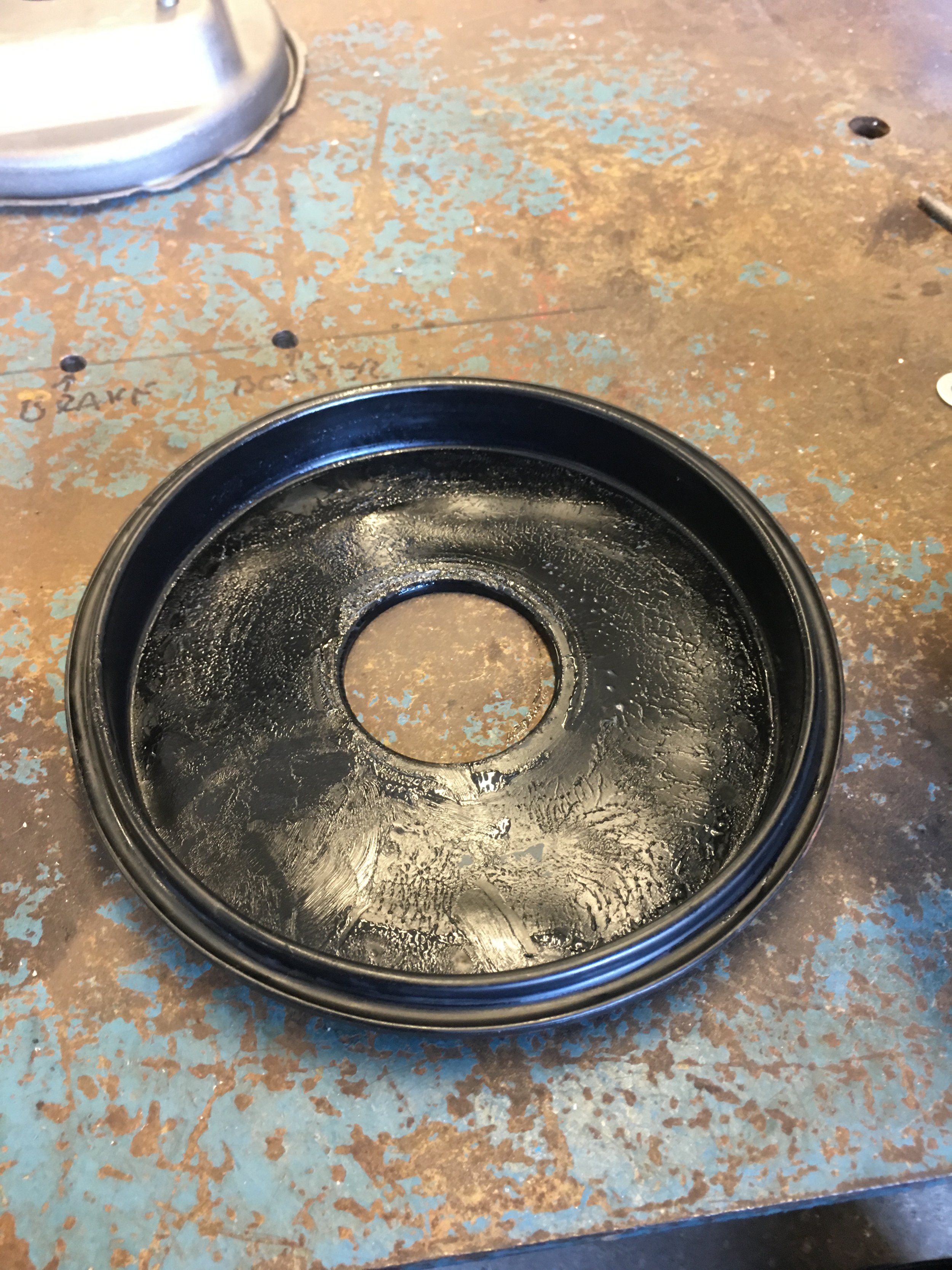
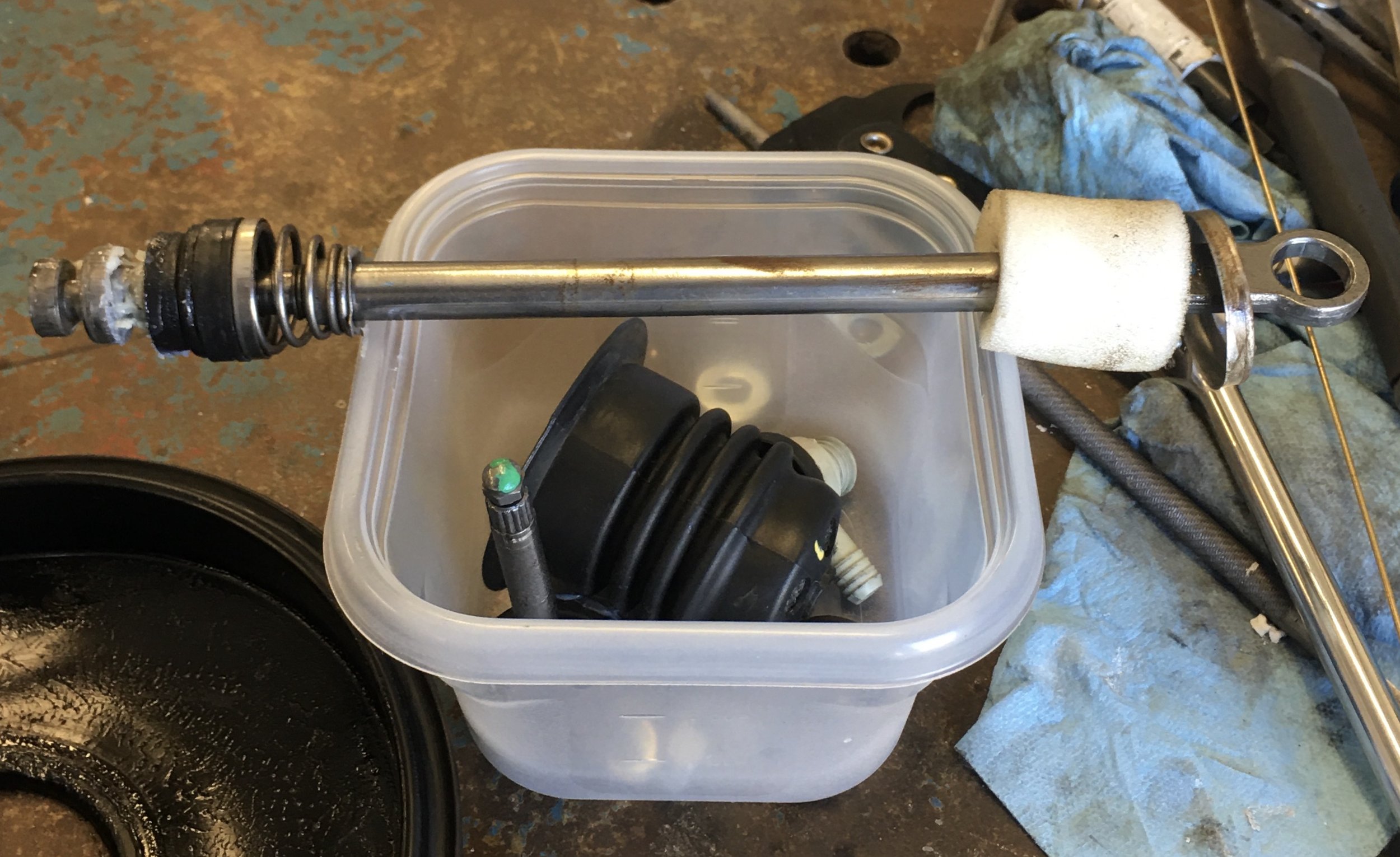
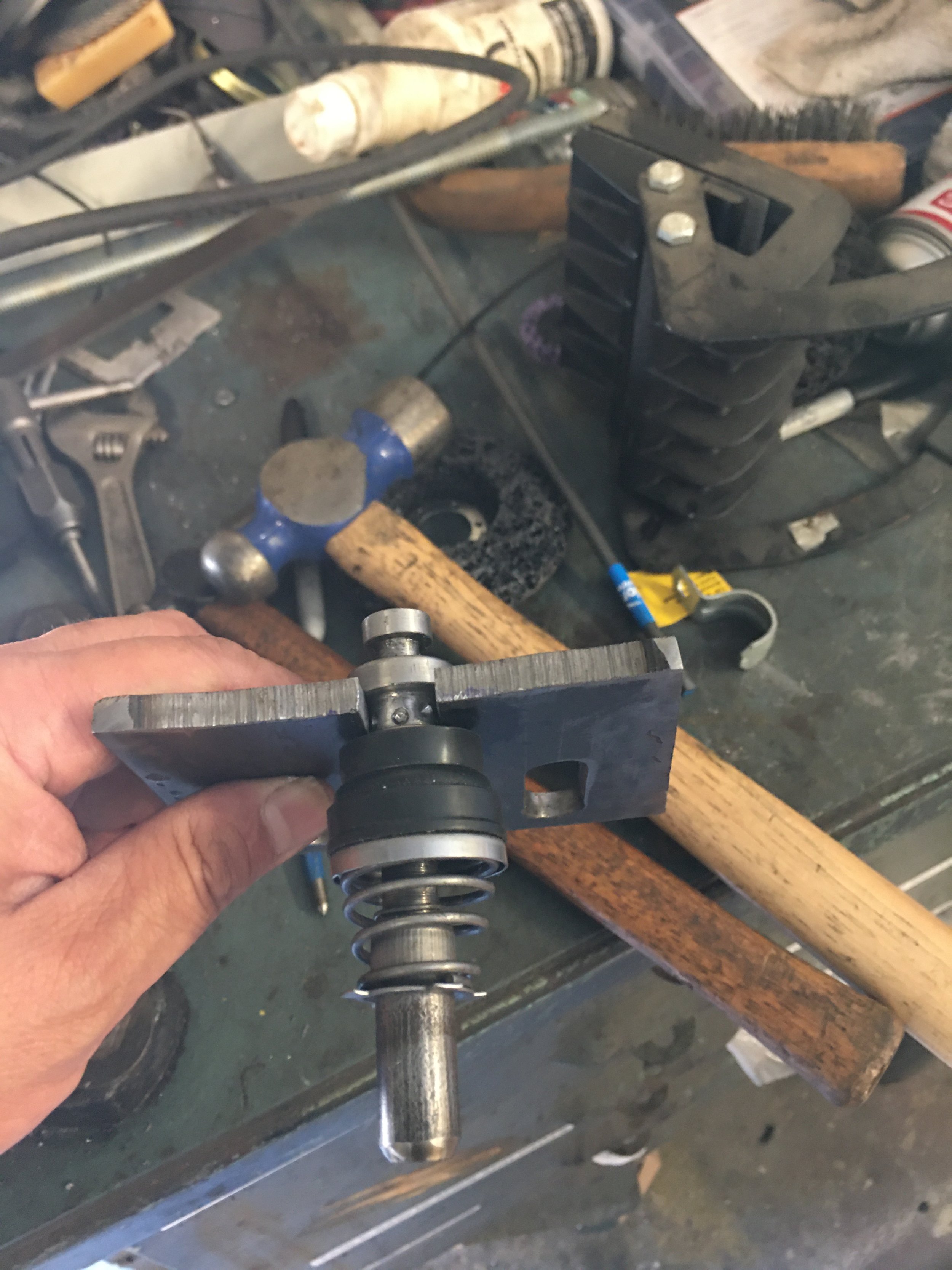
With the measurement taken, the booster was disassembled once again. The shells were put to one side and the internals were broken down even further.
One video I saw demonstrated the extraction of the push rod from the bakelite piston using a puller. I made my own using scrap pieces, all thread and a piece of PVC pipe.
I did try pulling the pushrod assembly out of the piston but it didn’t feel right, to much force was being exerted.
I saw another article on the disassembly of a brake booster and this one showed a clip holding things together. Hmm, Maybe.
I discovered the the diaphragm is not solidly attached to the piston, it just slips over it. Removing the rubber diaphragm revealed the clip holding the push rod in. Thank God I didn’t continue to try and pull the rod straight out.


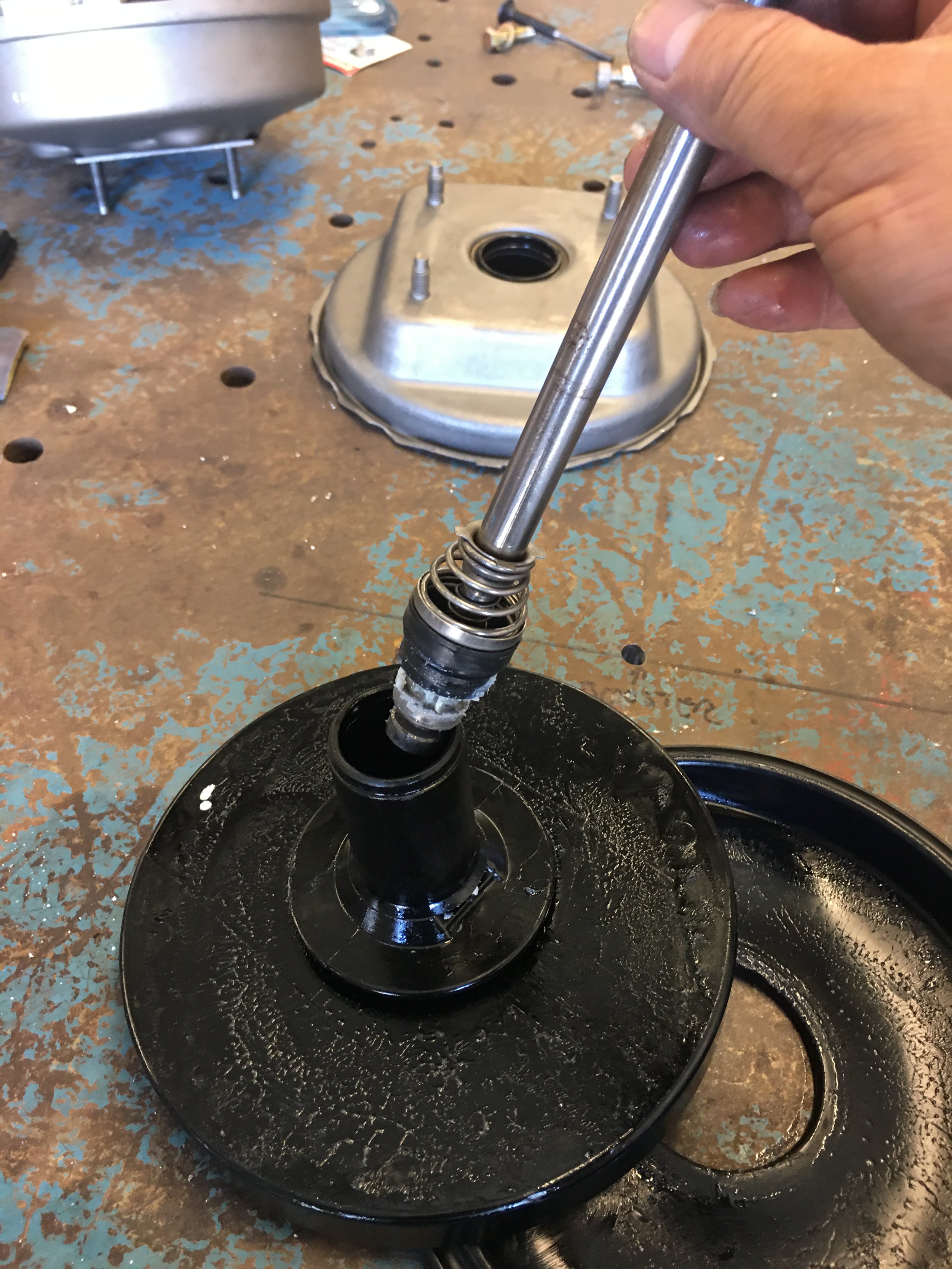

The push rod has an aluminum widget on its end. I think it’s part of a valve system that works with the piston. From the looks of it, this “valve” is held onto the end of the rod by staking it in place using a punch. This says, “pull me apart” to me.

Remember that rolling cart I’ve been using? That thing is full of threaded holes to hold various devices down on it. I think it was used for servicing large Air Conditioning compressors. The valve fits cleanly through one of the larger holes on the cart.
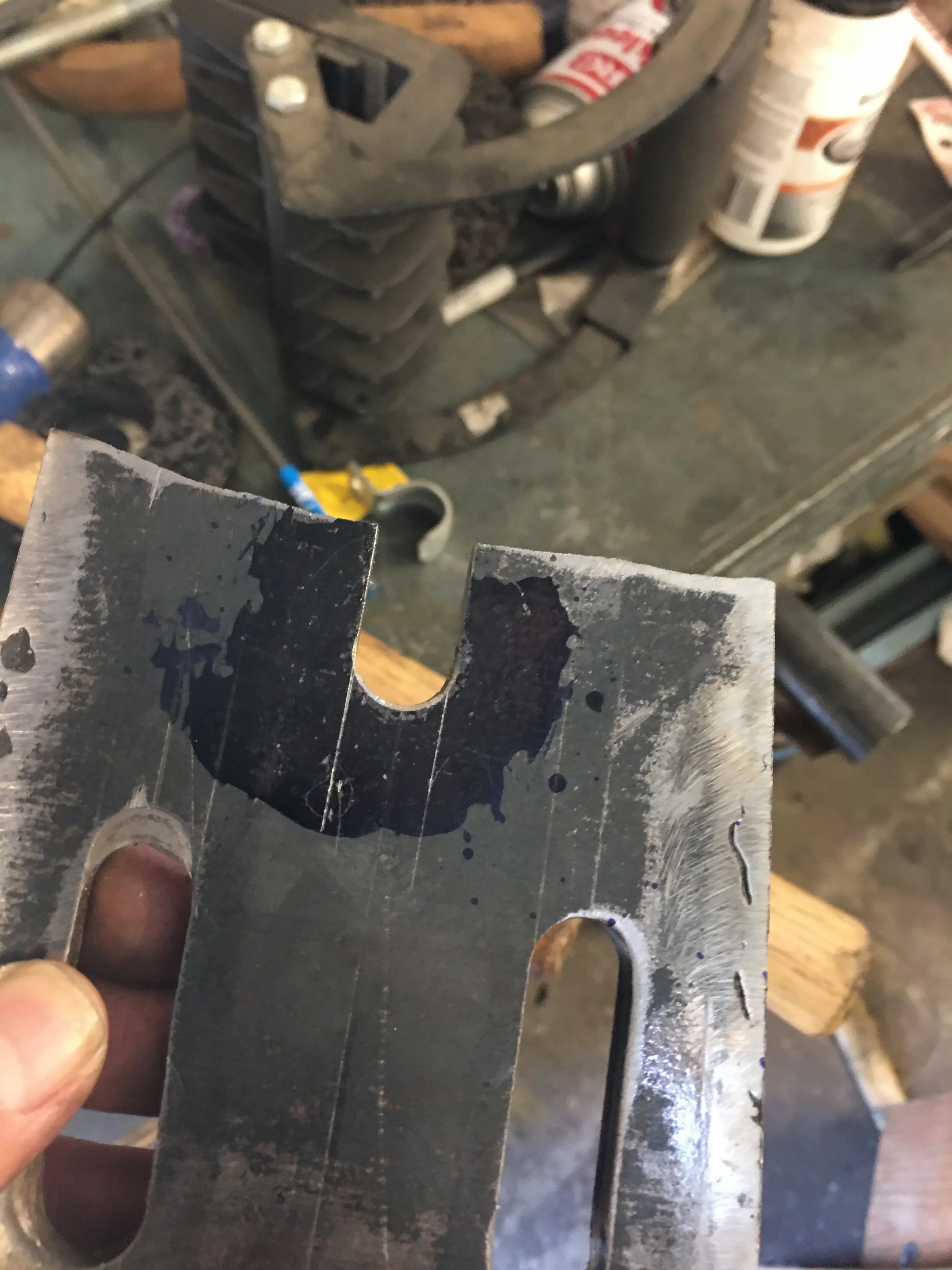
I made a clip that slides within one of the grooves on the valve. When the valve on the end of the rod is passed through the hole in the cart, the clip is slid into the groove so when the rod is pulled upward, the clip keeps it from being pulled out.


With the clip holding the valve in place, the rod puller can be used to separate the valve and push rod…I hope.
It worked!!!
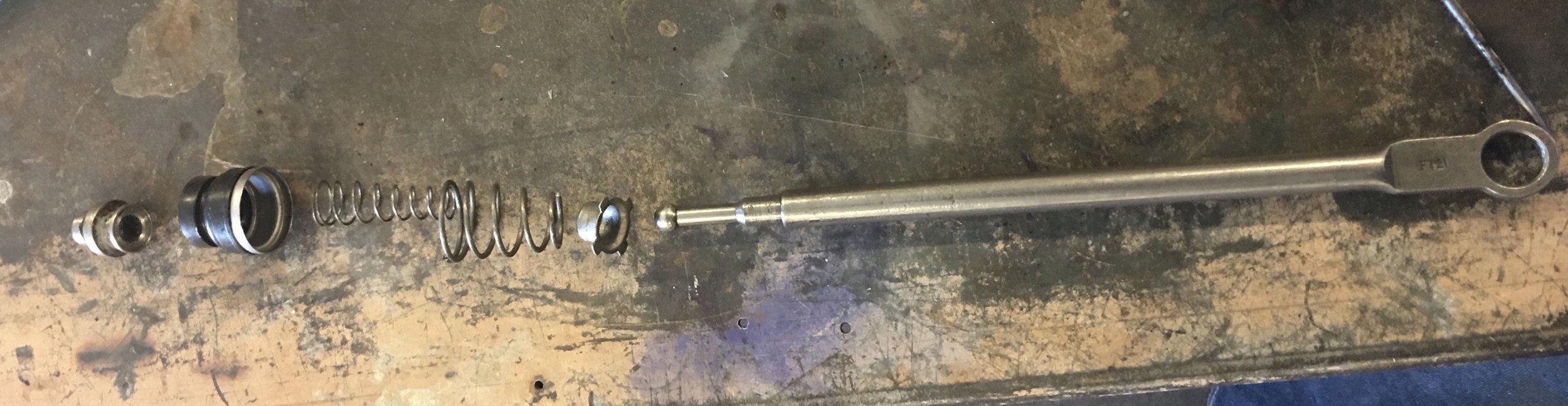
I can finally get to work on cutting this push rod to a length I can use for reals.
Once I measure the rod from the tip to the Sharpy mark, I’ll have an over all length that I need. I have to retain both ends of this push rod so I’ll have to take a section out of the center and splice the two ends back together.
Challenge accepted.
Going from memory, I think the rod was 10” long and I need it to be 6-ish inches in length.
The tricky part of this lengthening is the brake light switch. Instead of a simple switch with a button that gets pressed by a tab off of the brake pedal, the Mustang used an odd little design where as the switch fastens to the pin on the pedal arm. The the pedal is pushed, the is small amount of play that allows the pedal to move forward slightly before the switch attached to the pedal to engage a flat on the end of the push rod. Too tight and the switch stays on all the time. Too loose and the switch never engages.


Why do a job simply when you can make it complicated?
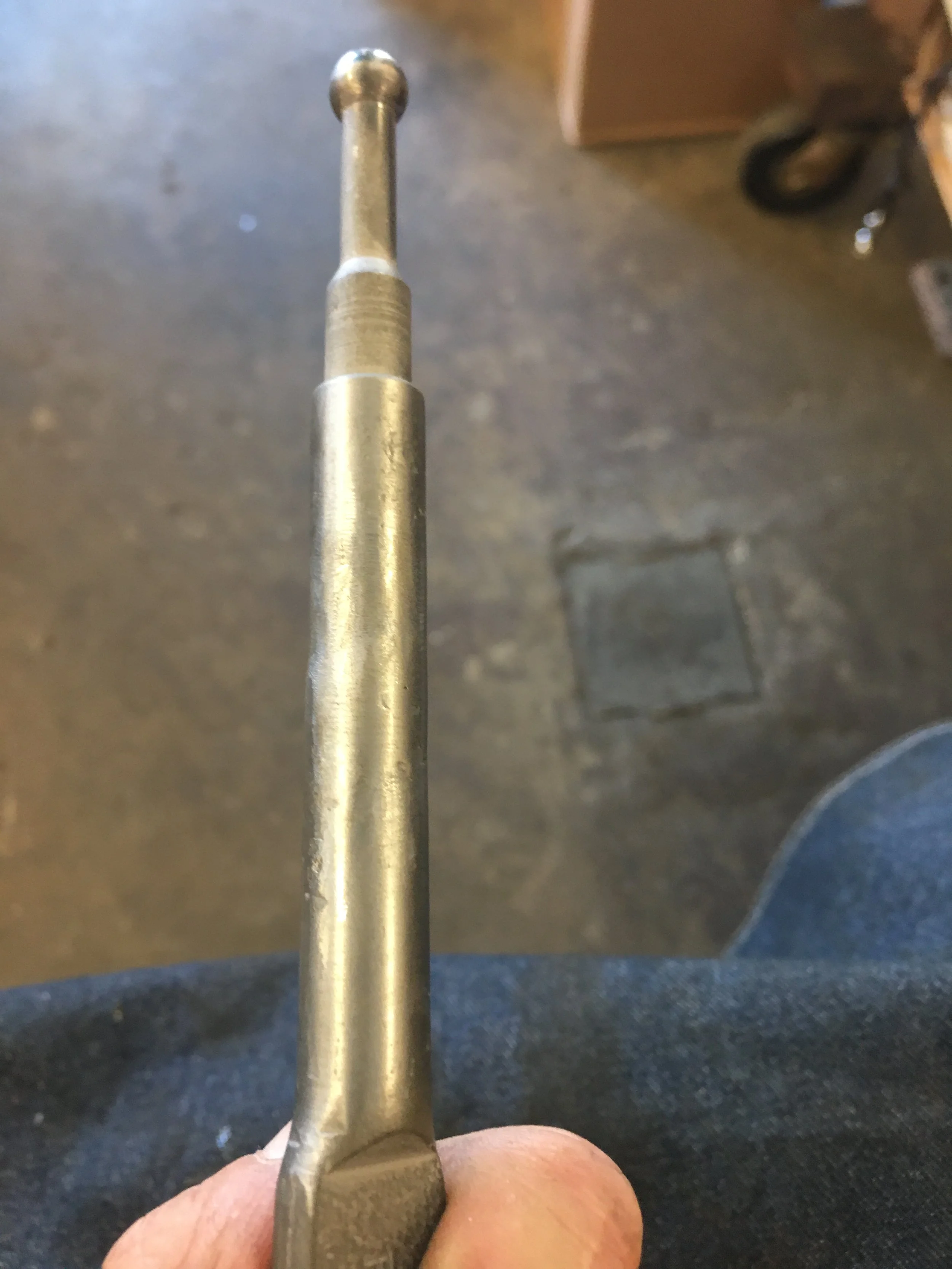
One mod is made before any cutting begins. The hooped end of the push rod needs to have a flat spot to engage the brake light switch. The end is built up with welding rod and then ground to shape on the disc sander. Now it’s ok to start cutting this thing apart.


I made a discovery with my Sears Craftsman tap and die set. In the past when I tapped out a hole for a bolt or all thread, the fit always had a little play. The same thing if I threaded a piece of rod and put a store bought nut on it. I discovered that if I were to drill and tap a hole with the tap from a tap and die kit and then used a die cutter from that same kit to cut threads on a piece of bar stock, the finished product has a very solid fit.
When I bring the two ends of the dissected push rod together, I wanted the two pieces to be screwed together so I could have the ability to adjust the length of the rod by screwing them in and out before welding the two halves together.


The ends were chucked in the lathe and using the end stock, the ends were bored so they can be tapped for a 5/16-18 threaded shaft. Instead of all-thread, I have a lot of those 3/8” carriage bolts. The heads were cut off of a couple of these bolts and then the shafts were turned down to 5/16” OD. This 5/16” shaft was then threaded using a 5/16” die from the Sears Craftsman thread cutting set.
Note: When cutting the threads on the bar, go slowly. I mean ridiculously slow. On this size of bar, too zealous of cutting will actually twist the shaft with every turn of the die. I burned through two of these before I got it right.
With everything threaded, the three pieces were fastened together. The fit was very solid but the pieces came together a little bent, a few taps on the high spots as the rod is rolled across an anvil makes the rod pretty straight.
It’s slow, frustrating work but the adjustable rod is reassembled with all of its parts, reinstalled into the piston and then the booster is reassembled. Next, the booster is installed back into the car and the push rod length is checked.
The booster had to be taken apart a couple of times to make adjustments to the push rod, one of which was restaking the aluminum valve device at the end of the rod. It was causing too much end play without doing that.


With the length figured out, the push rod was completely welded and the weld was cleaned up to take the ugly out of it.


The booster was assembled for the last time…or that’s what I thought until the vacuum tests were performed.