
Boost X2
***This post focuses on heavily modifying the power brake vacuum booster. DO NOT ATTEMPT ANY OF THESE MODIFICATIONS. This is to be read for entertainment only. Tampering with the factory structure could lead to brake failure and can endanger your life and those around you.***
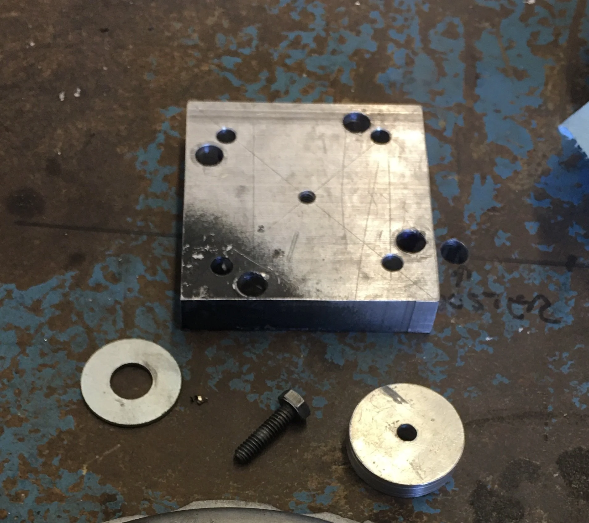
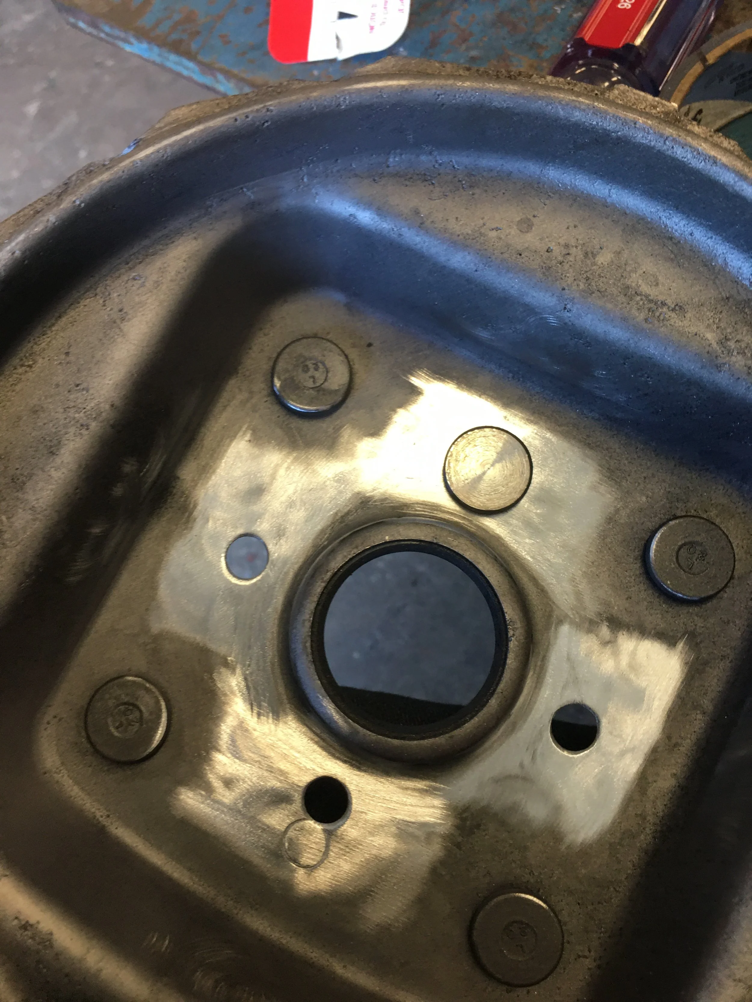
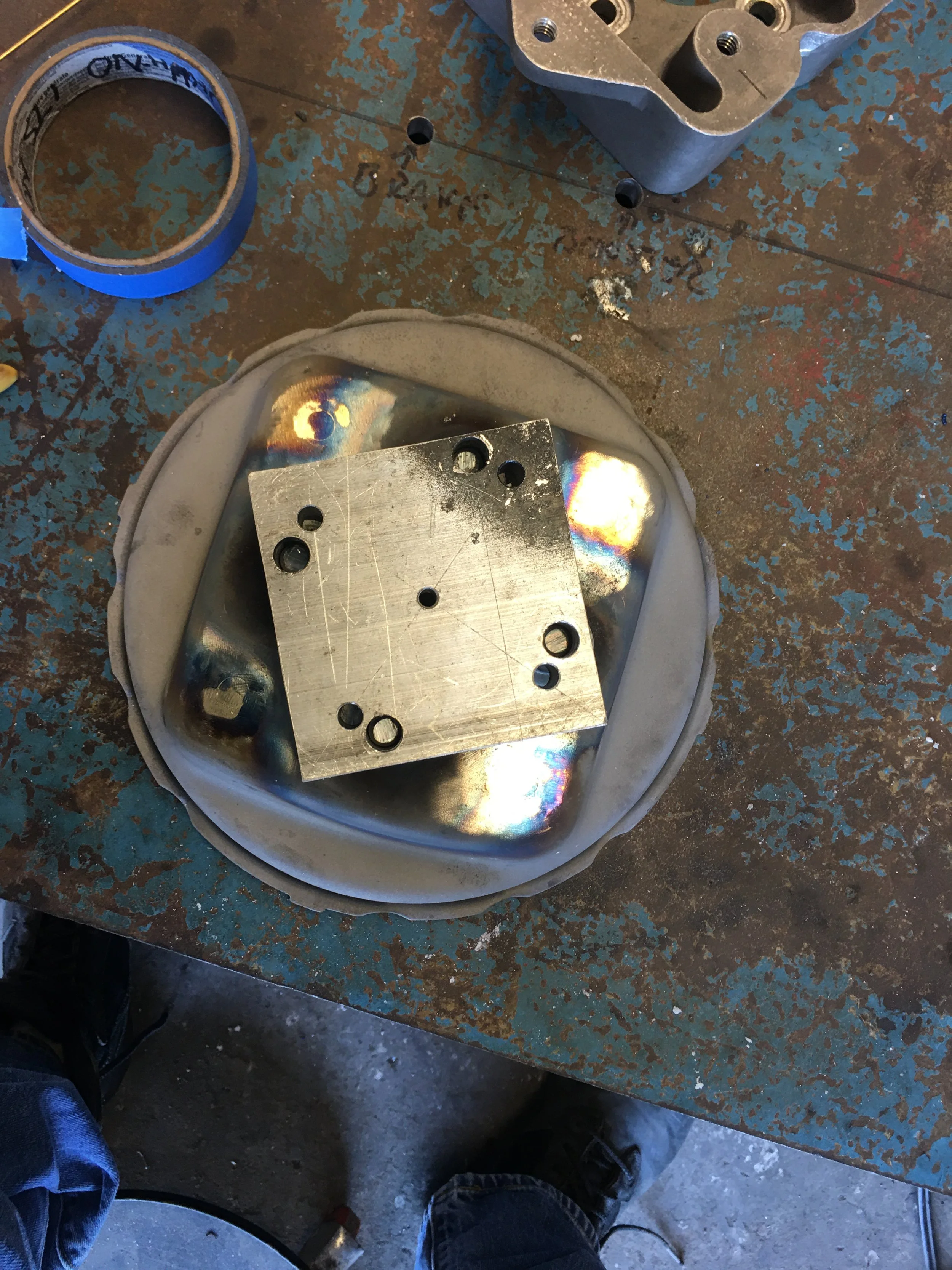
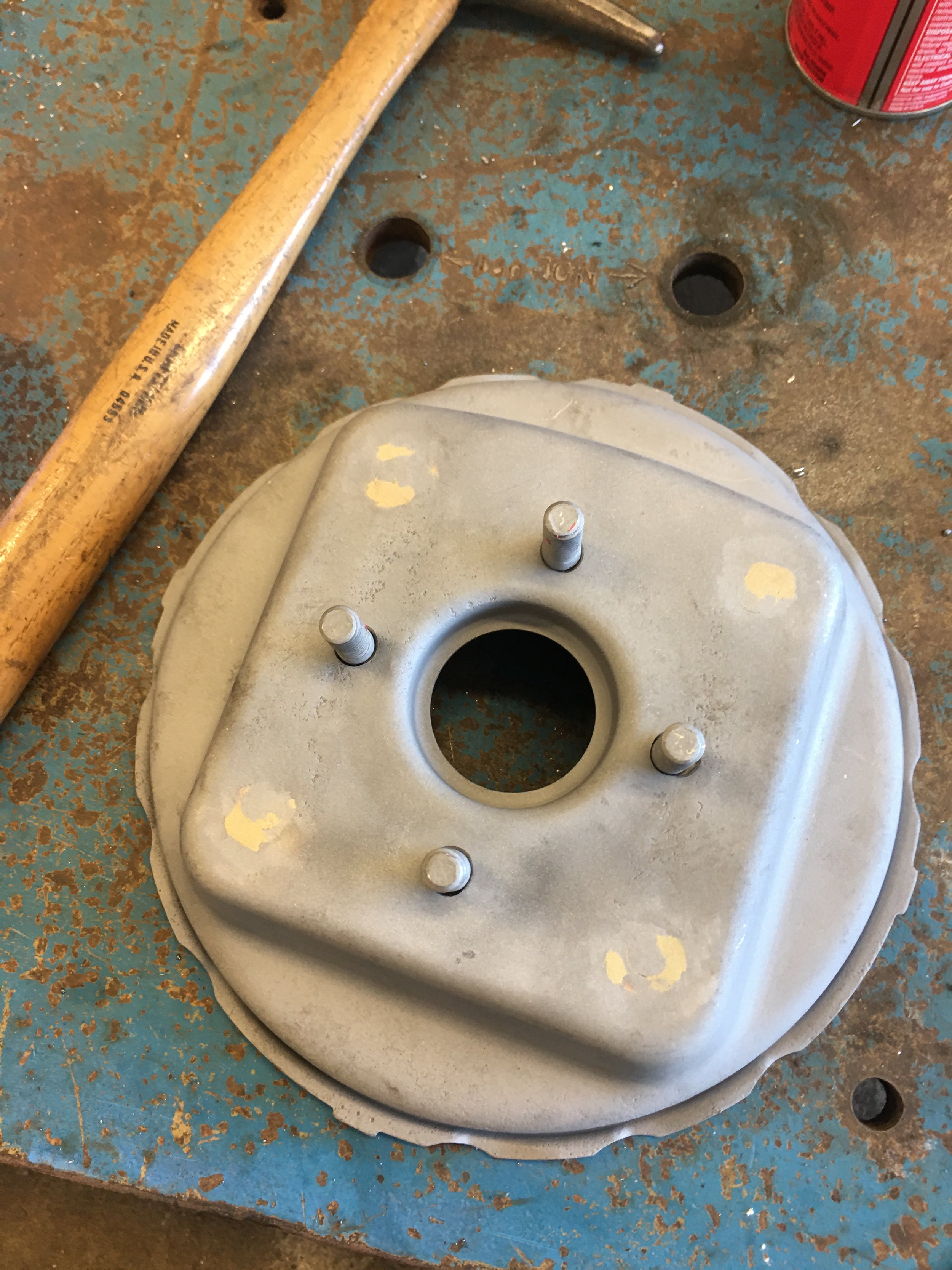
The aluminum Jig thing has been modified as mentioned before to correct for the off-set of that stud that hung up the wedge from clearing all four studs on the booster shell.
In order to keep from subjecting this new shell to too much heat, the old studs will stay and new ones will be used instead.
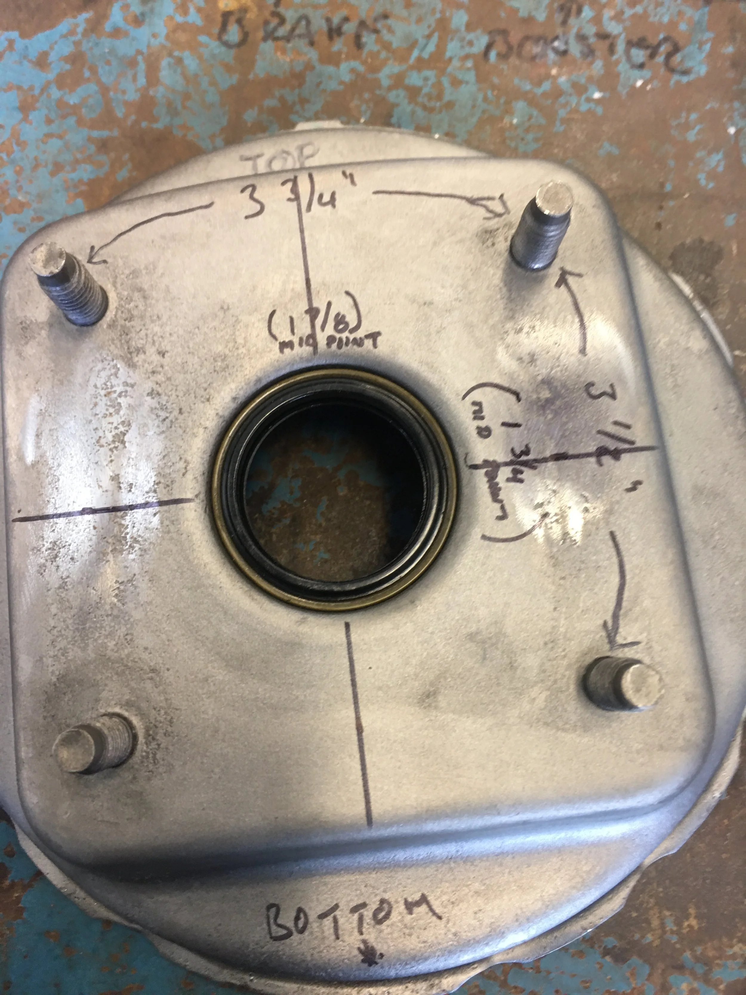
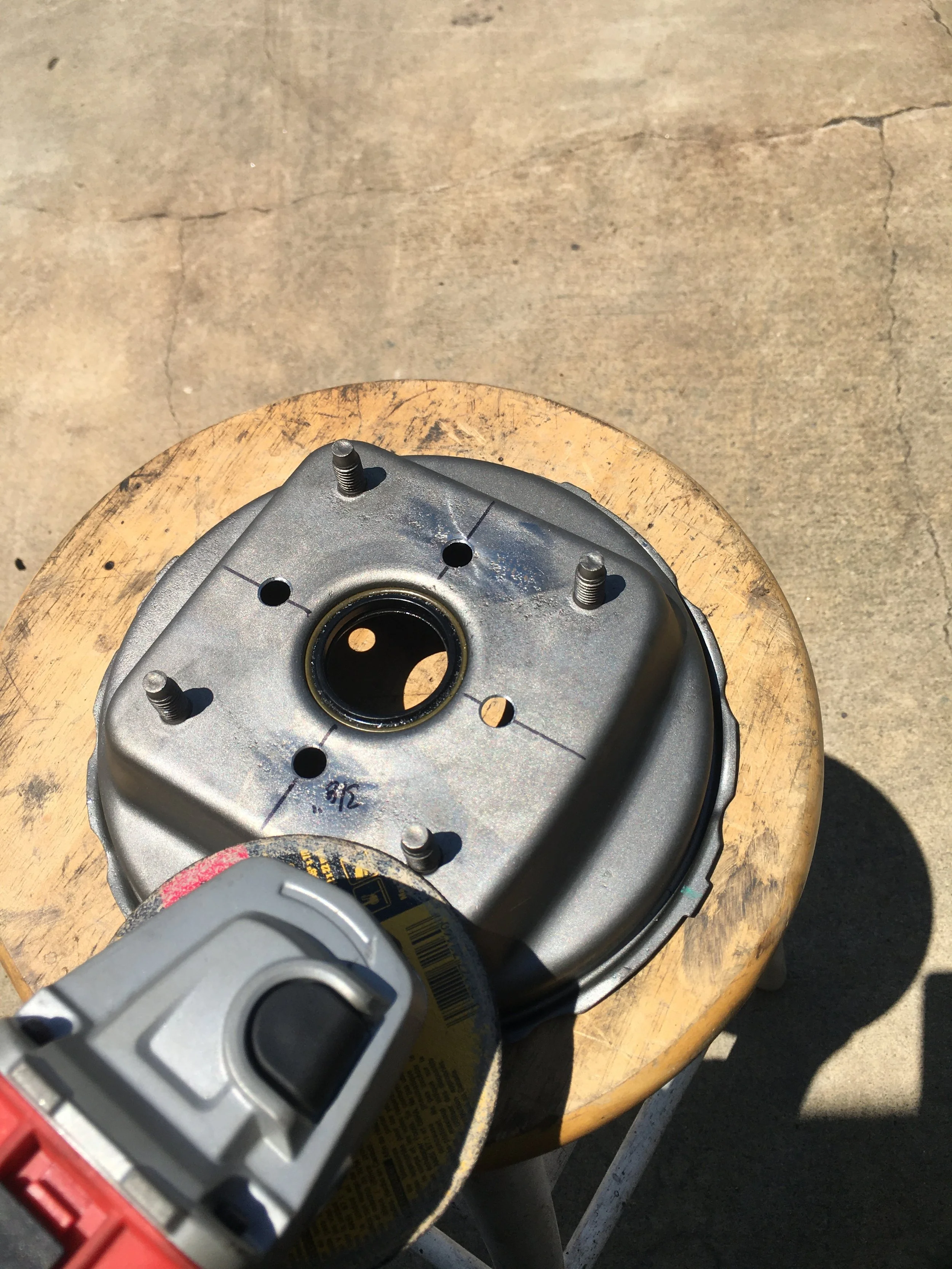
The new shell is marked up with a Sharpy. Measuring the the distance between the existing studs, the center point between each pair is marked and a straight edge is used to connect them in an X-Y fashion.
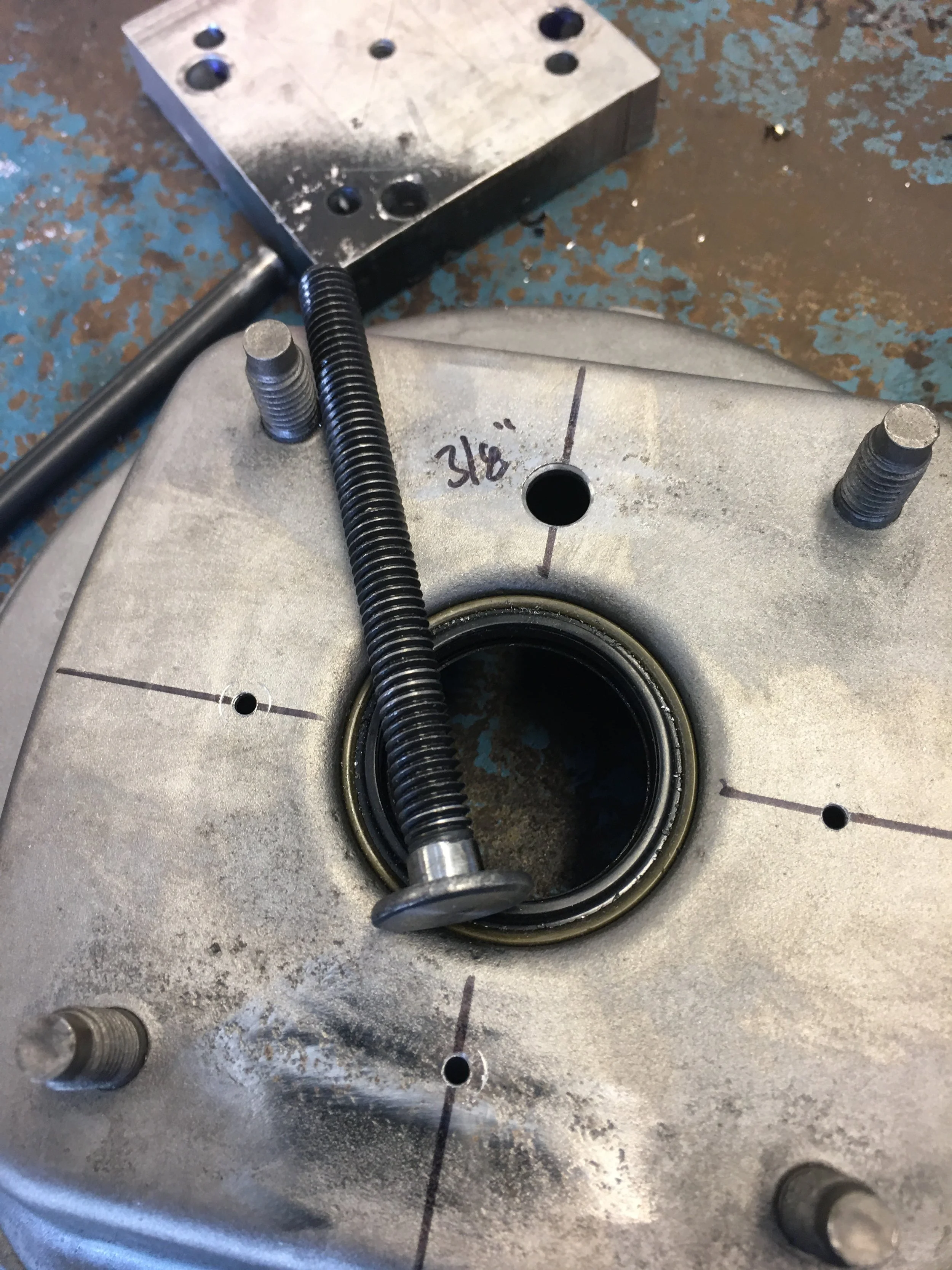
The centering plug is inserted into the center of the seal in the shell, the seal is pretty stiff and does not deflect all that easily, plus it holds onto the plug quite well. I included a washer as a spacer. The plug is slightly recessed into the shell. The washer keeps the jig from pulling the plug up when they’re bolted together.
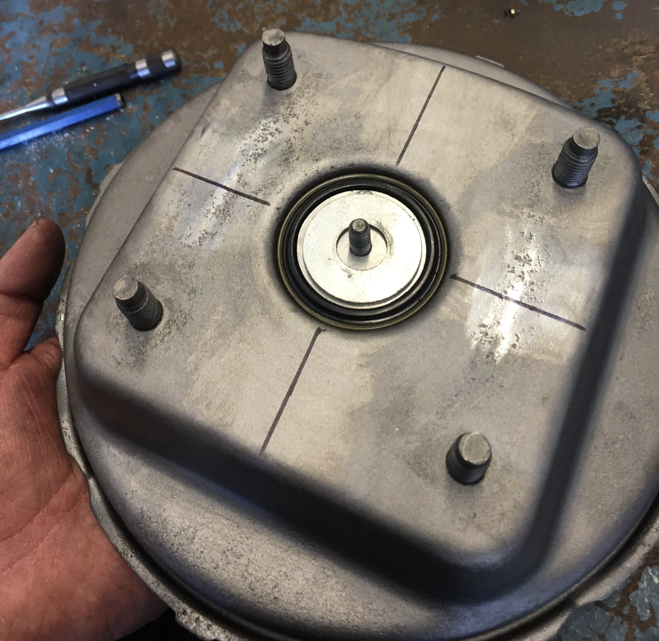
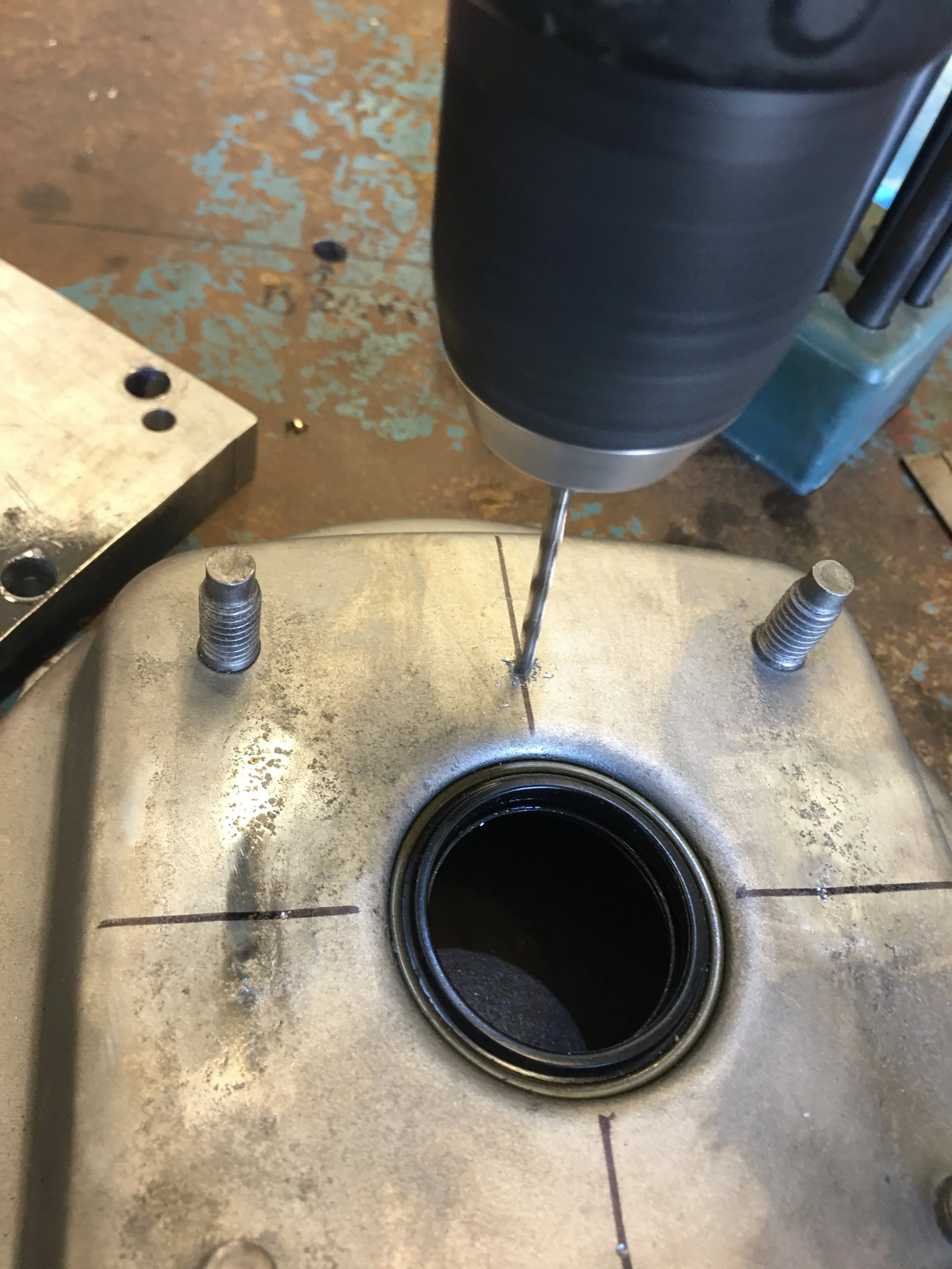
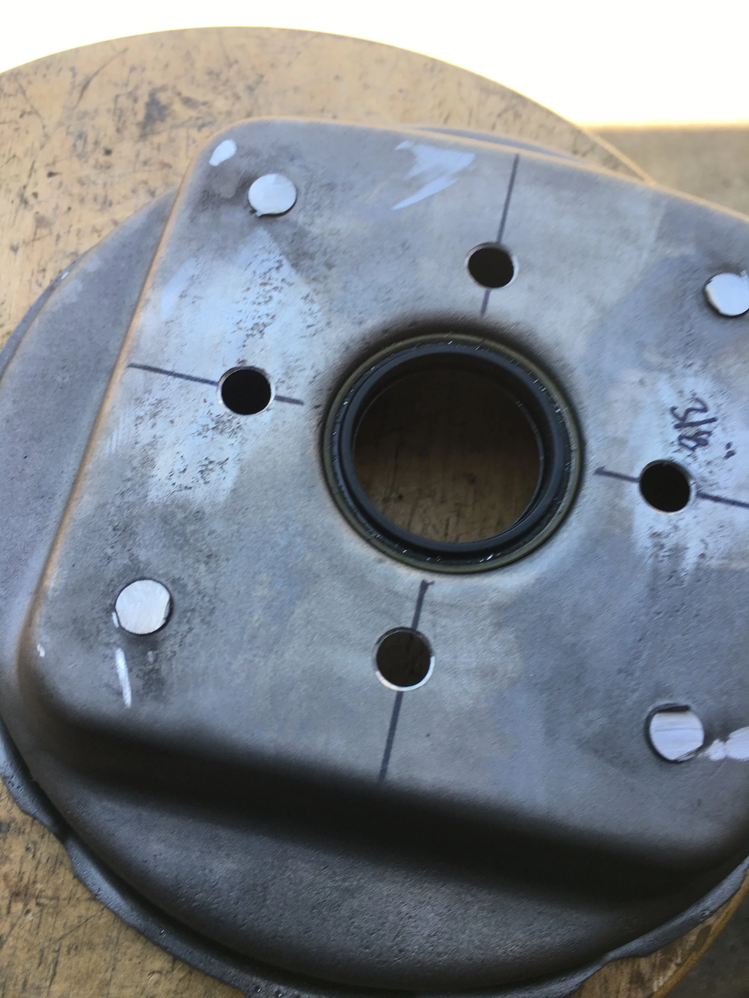
The reference lines are visible through the 3/8” holes in the jig, centered and then the location of the new hole is marked with a transfer punch.
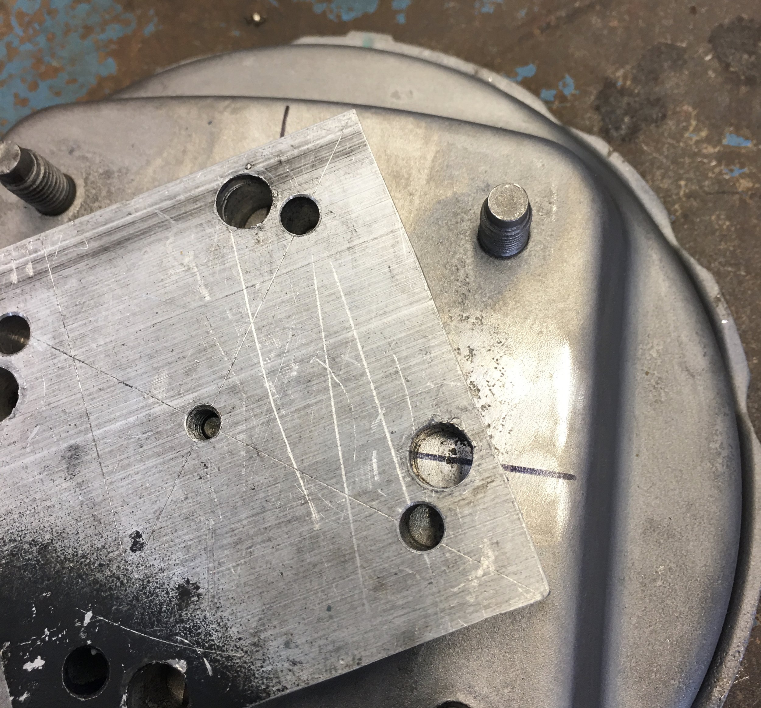
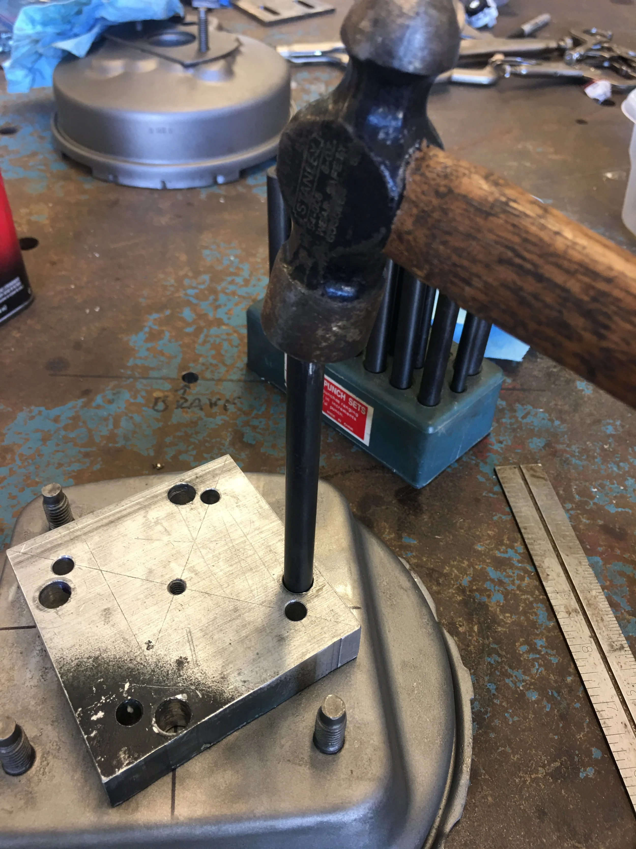
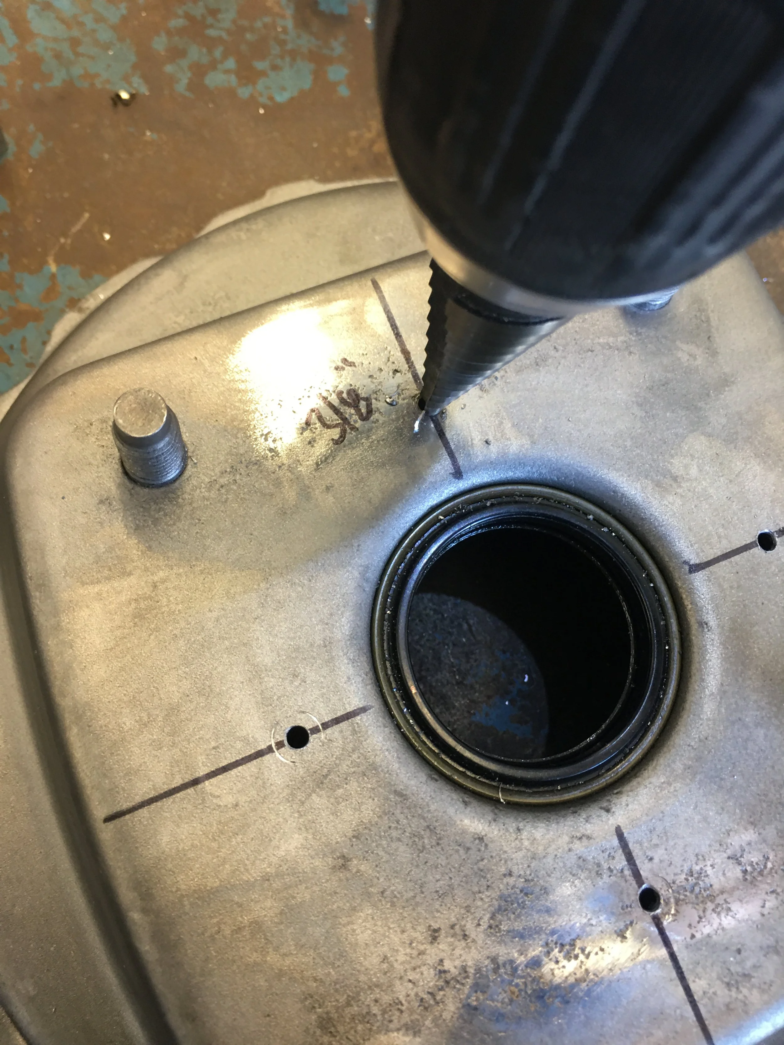
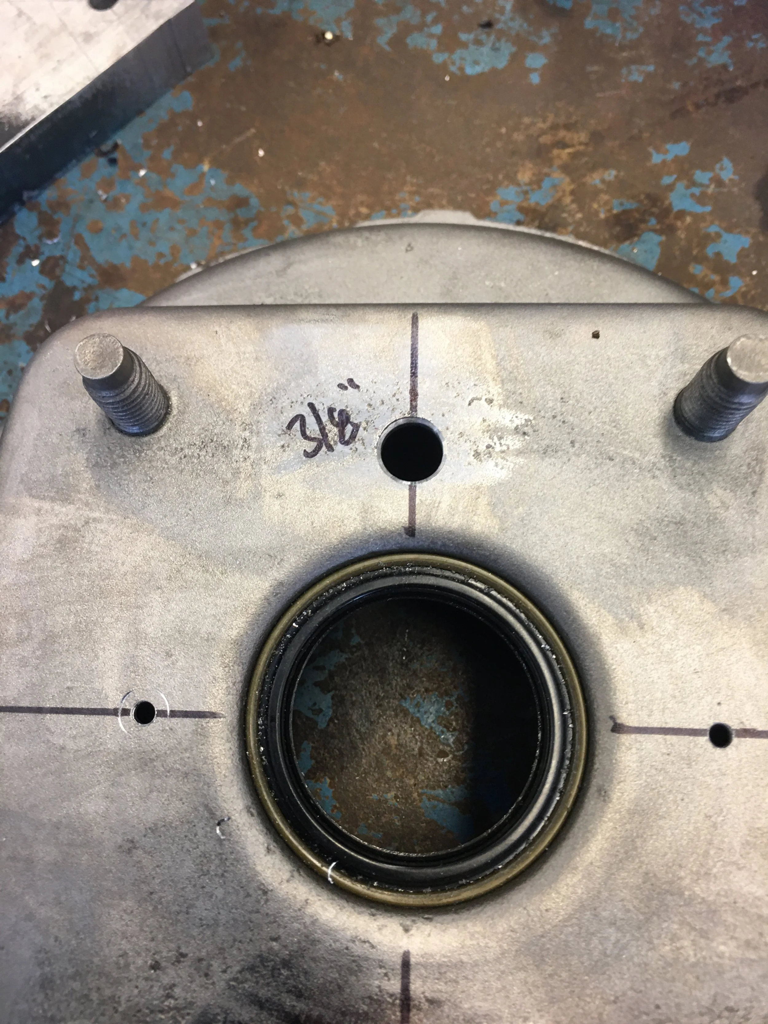
The locating jig is removed and the punch marks are drilled through with an 1/8” drill bit. This is followed by the Uni drill and cut to 3/8”
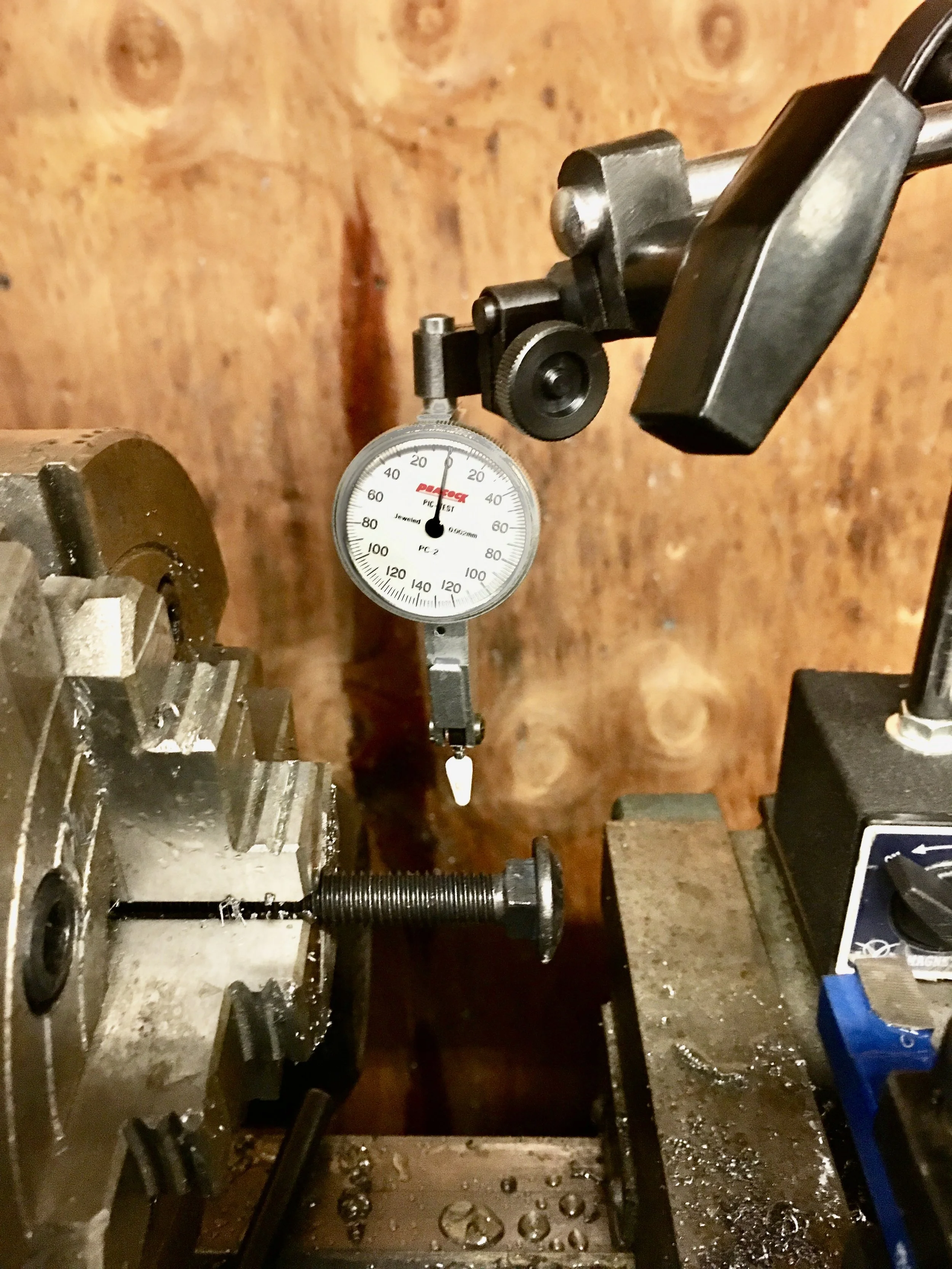
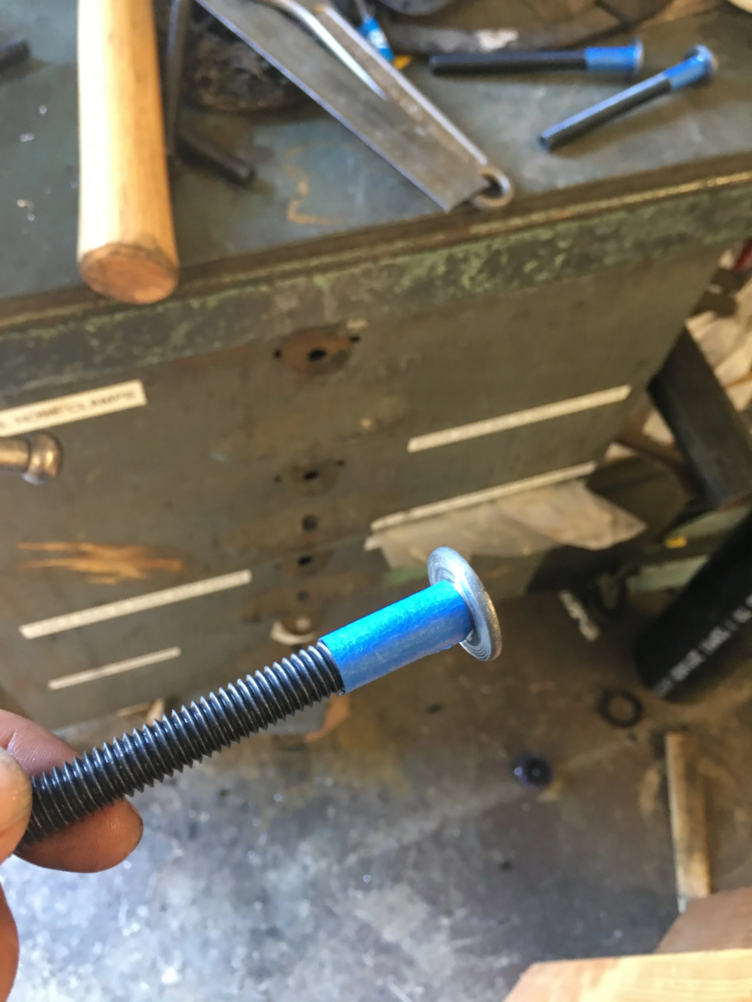
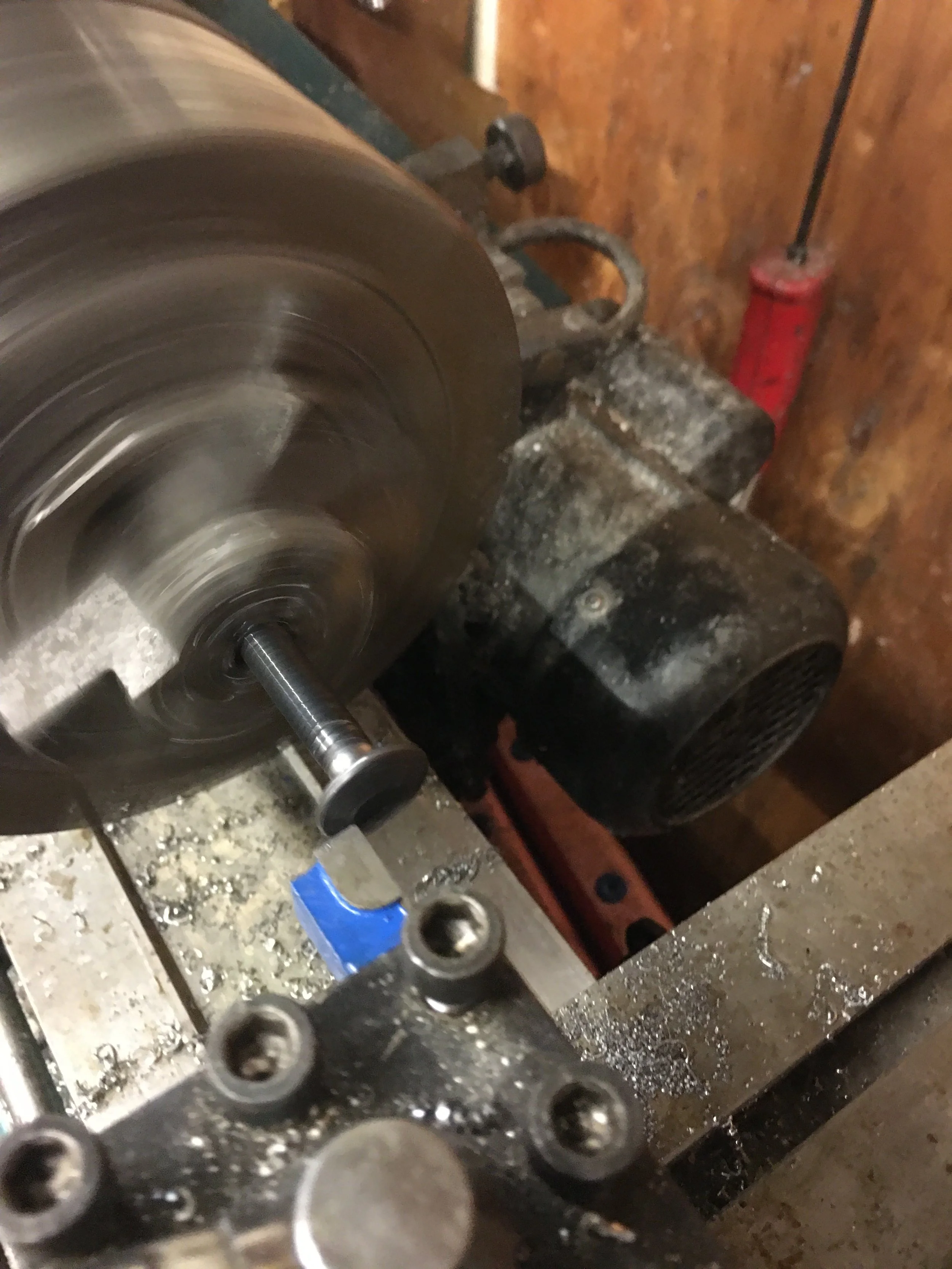
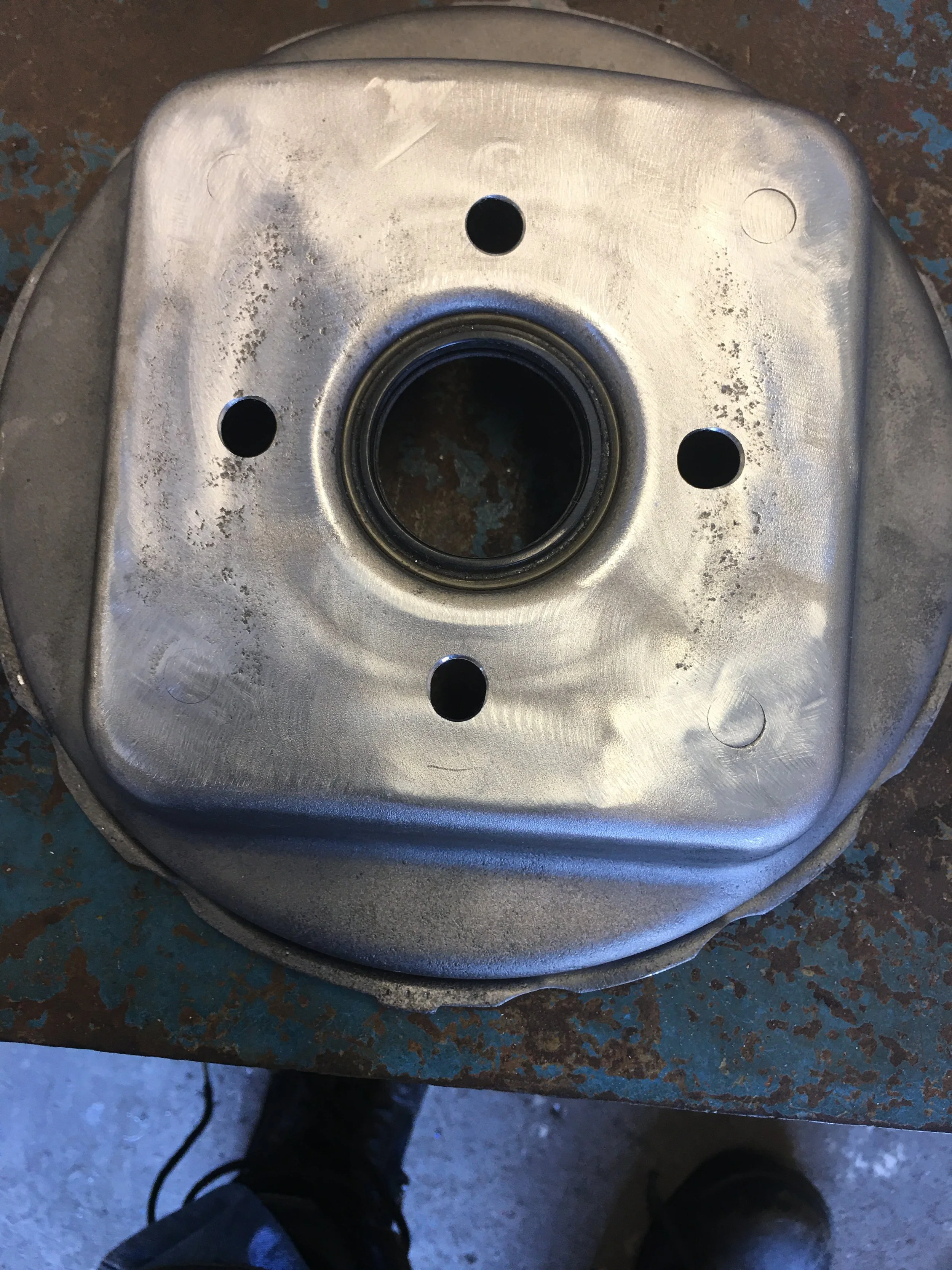
A modified carriage bolt is used to test fit the hole. I’m testing the modified bolt as well.
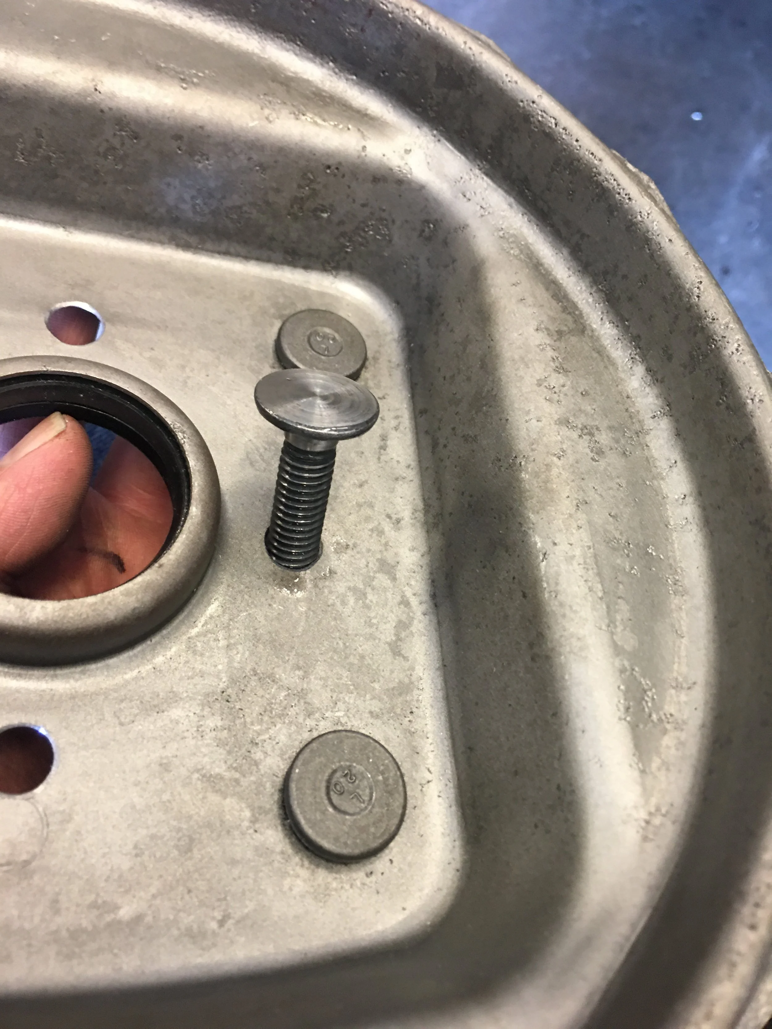
The fit is good. I can proceed to cutting the rest of the holes and finish modifying the carriage bolts into studs.
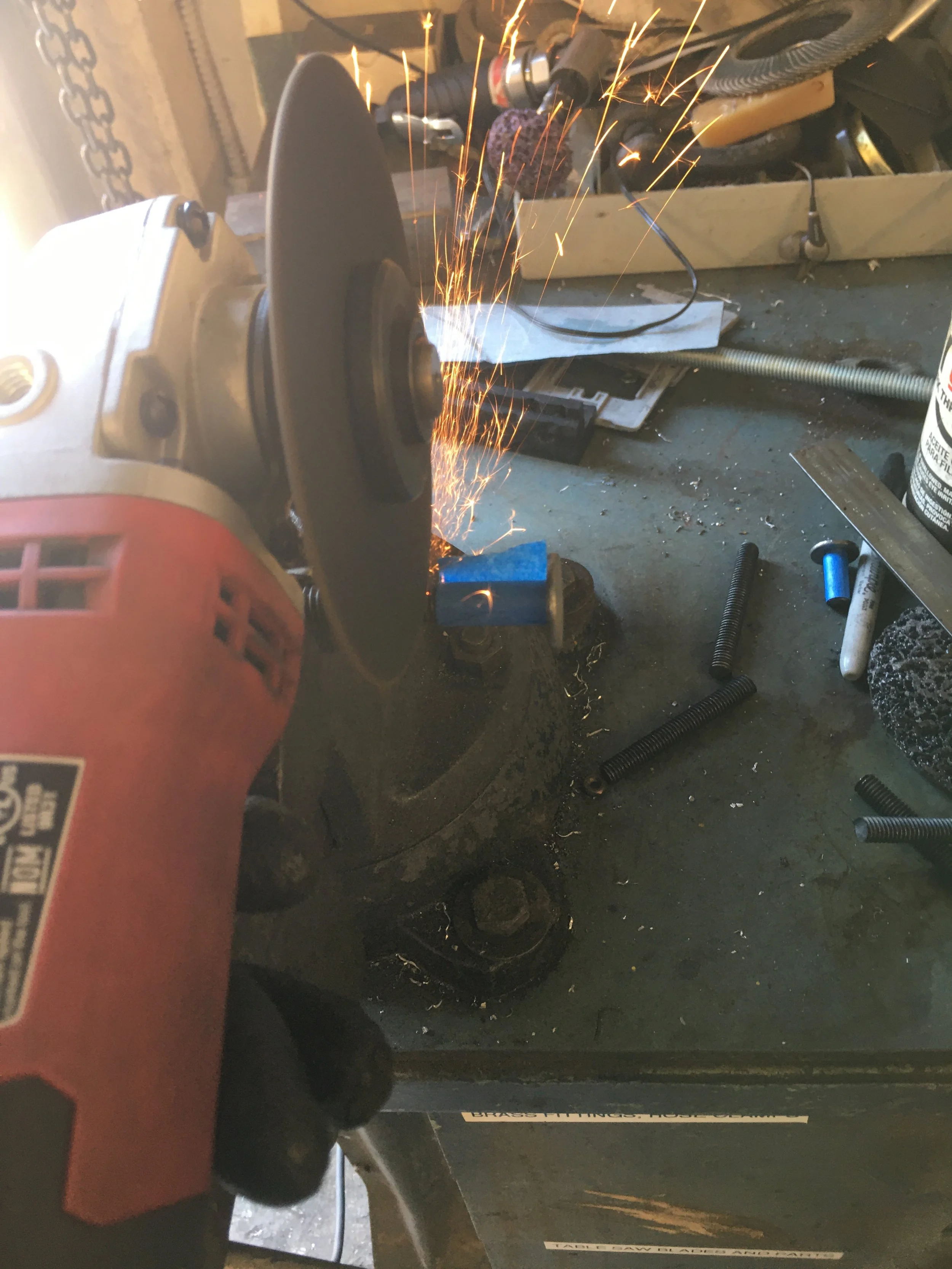

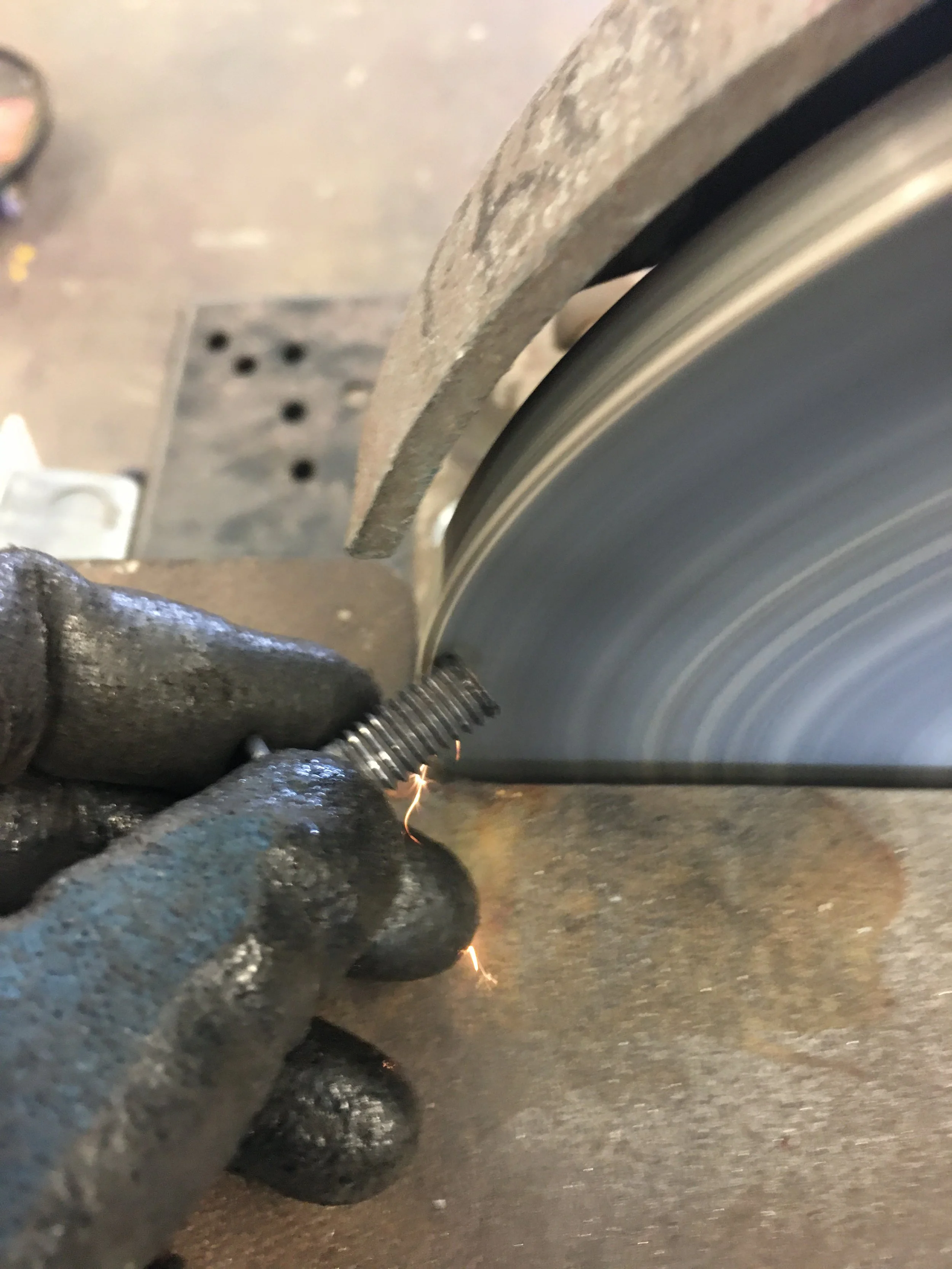
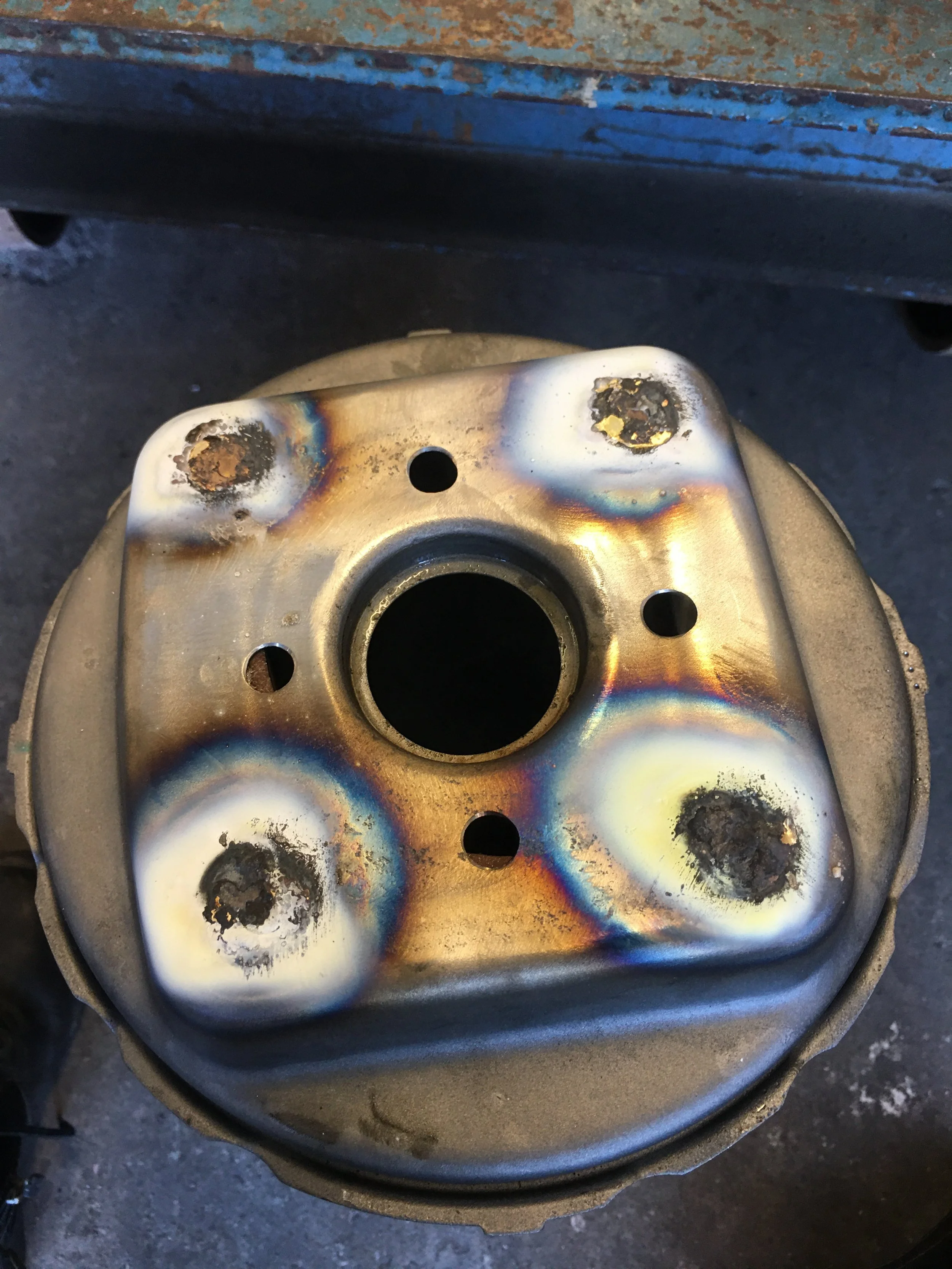
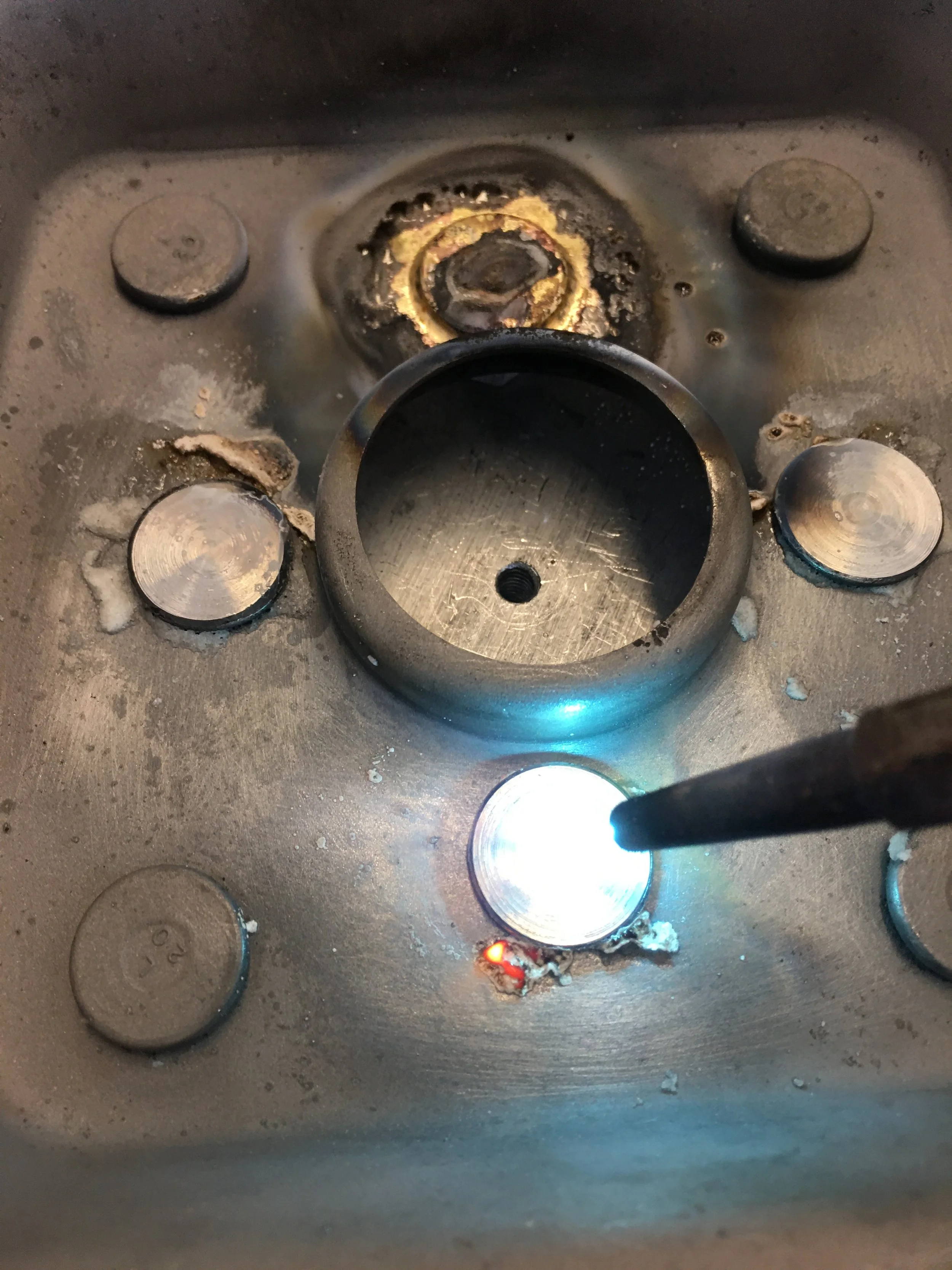
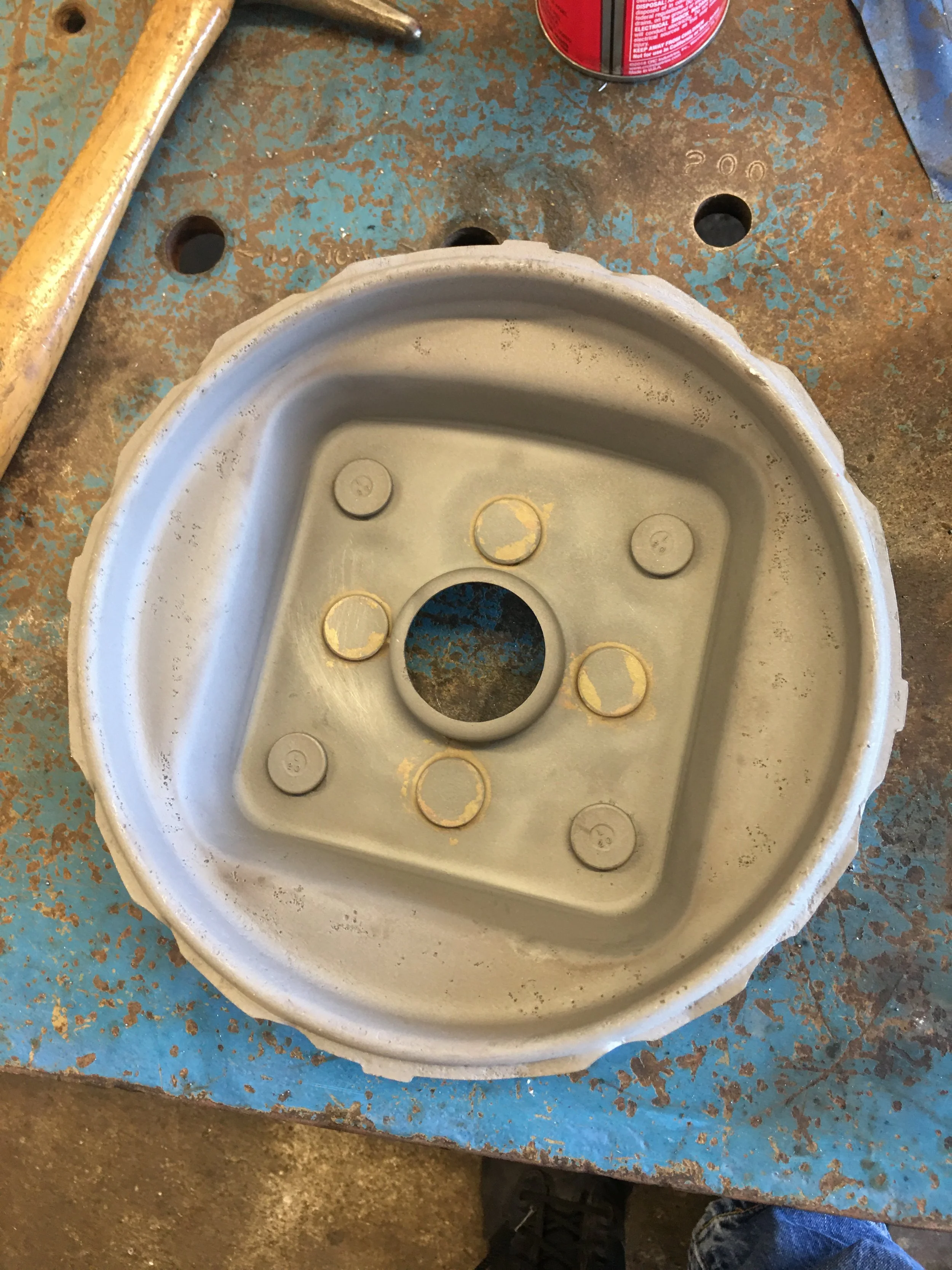
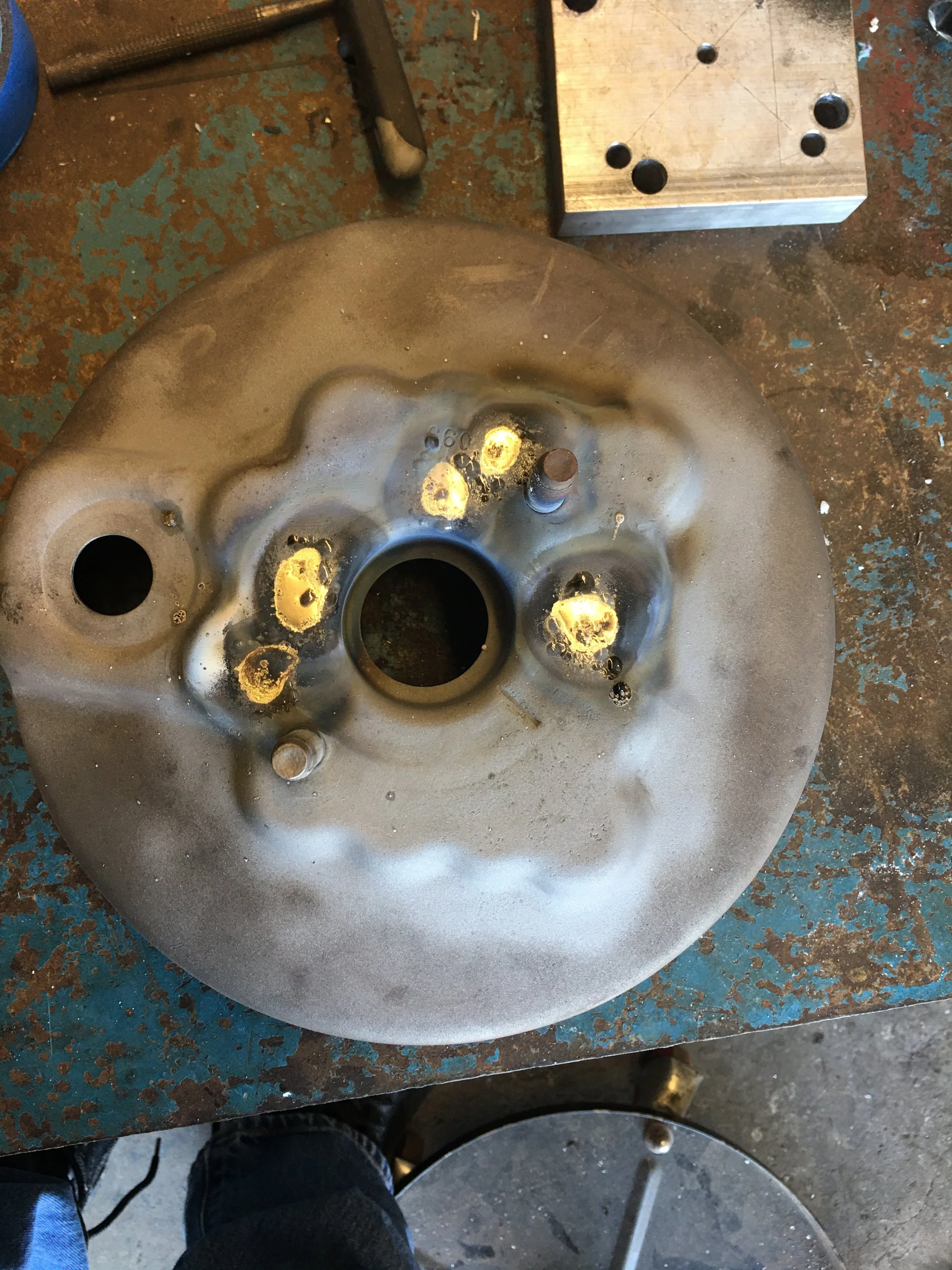
Breaking out the angle grinder again, the old studs are cut flush with the surface of the case and then the entire face of the shell was cleaned up with a flapper disc to ensure a better weld.. The metal on the inside of the case around the 3?8” holes were also cleaned up but with an air grinder.
There are low spots around the remnants of the old studs. I want to practice my brazing some more so I flow some brass filler around the four corners and clean them up with the air grinder…again.
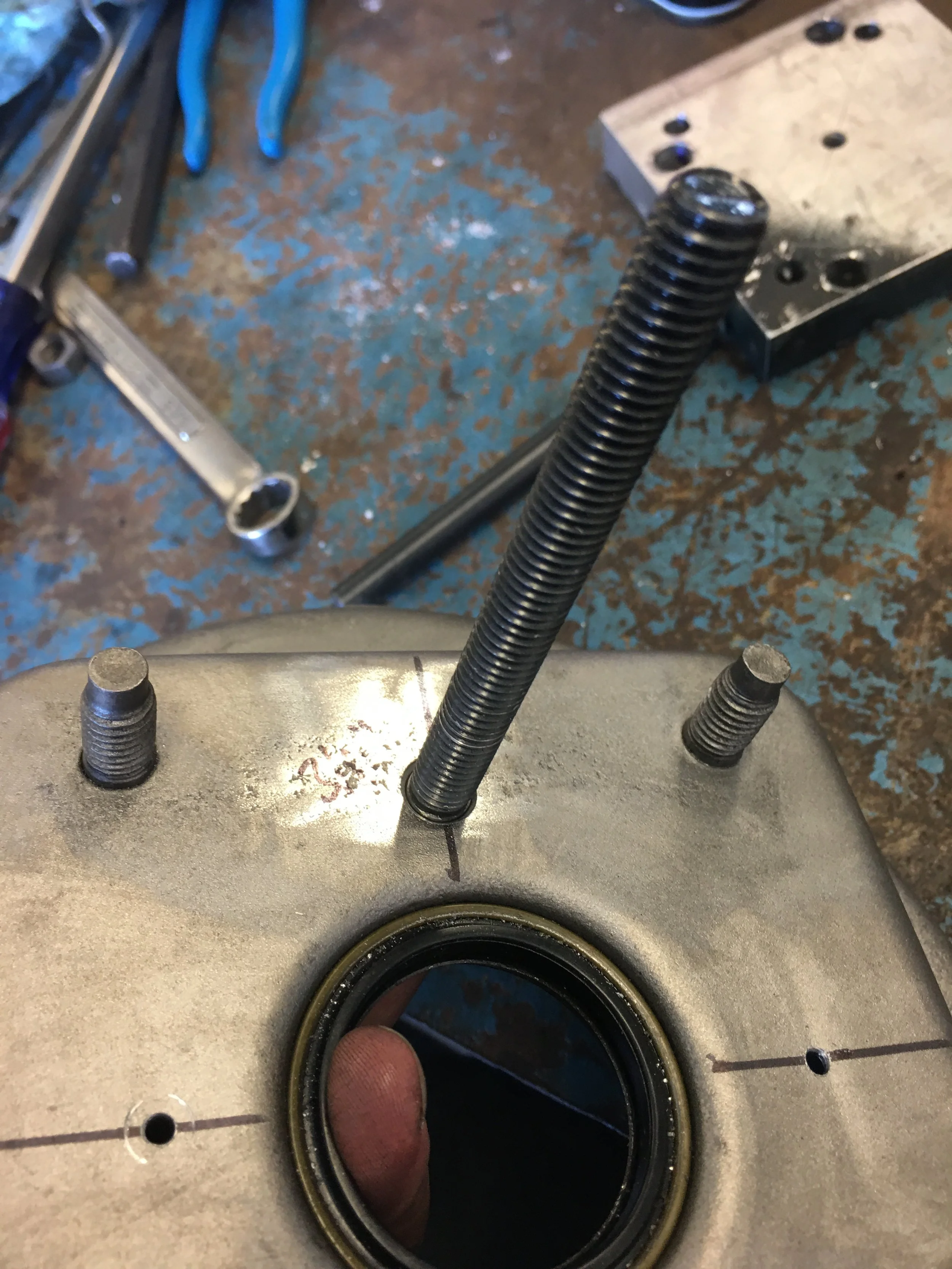
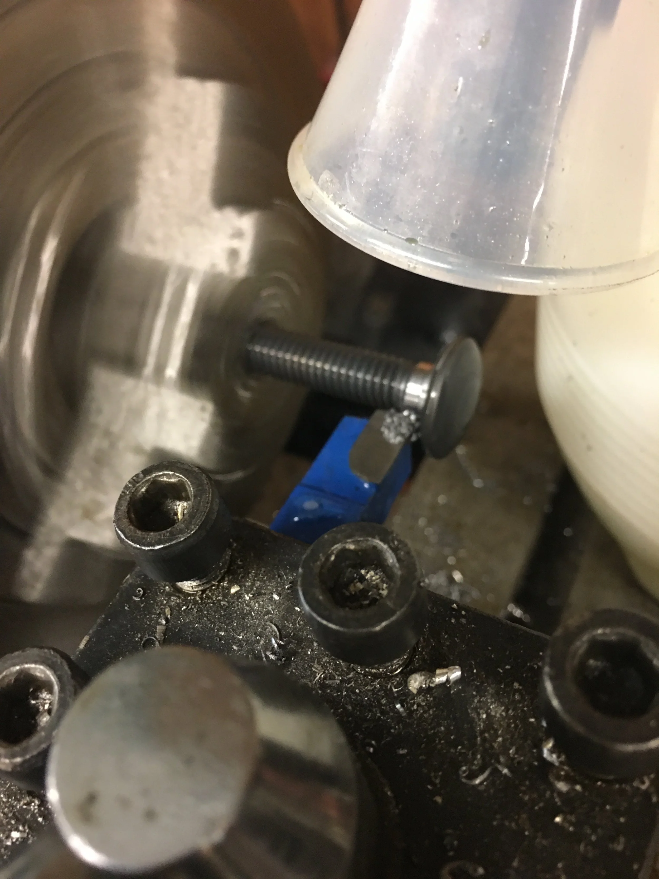
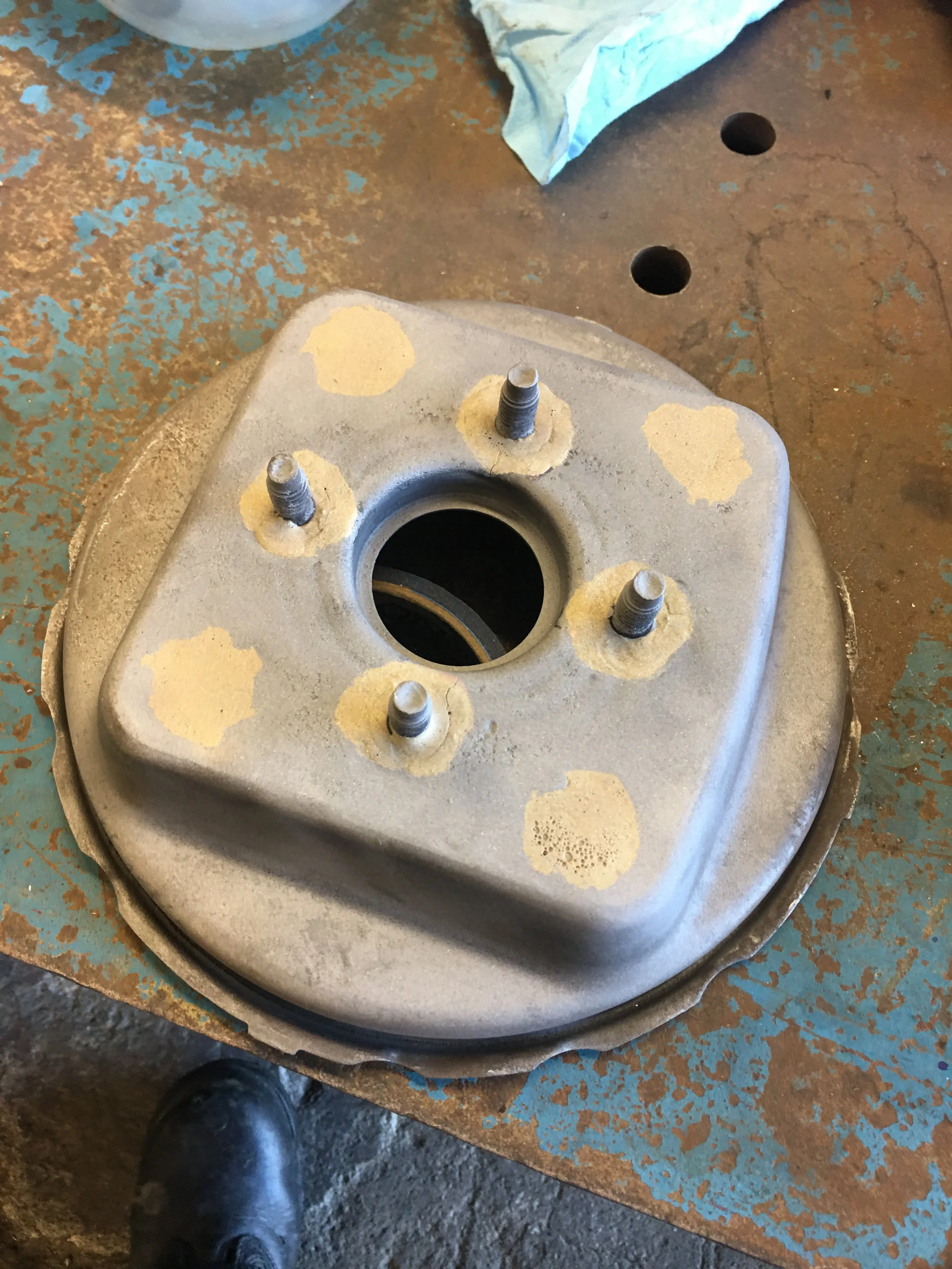
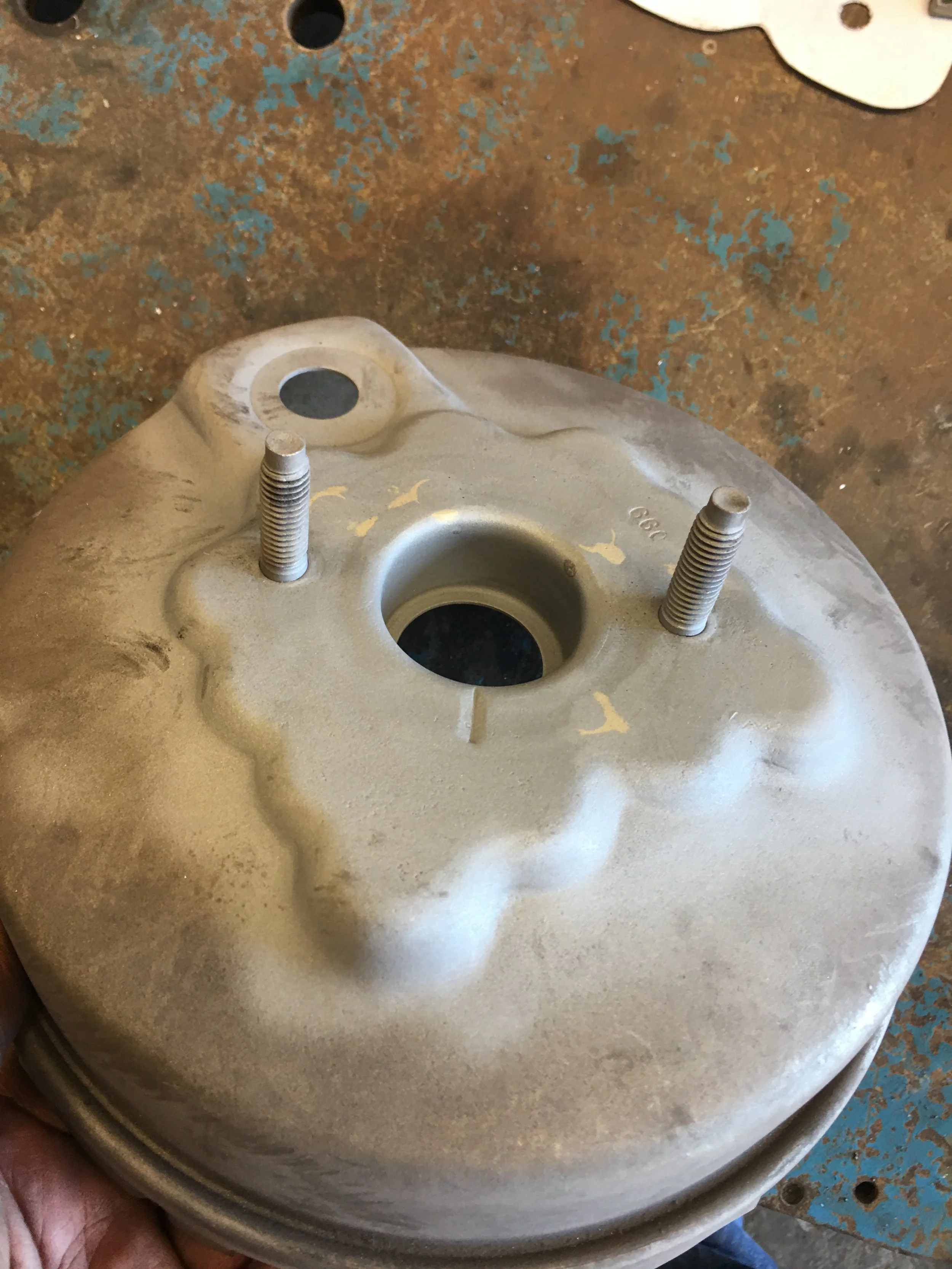
Finally, I can put the new studs in.
I was hoping gravity would help hold the studs in place but in the end, nuts and washers secured the studs in the booster shell. The aluminum jig was placed over the 4 protruding studs to ensure alignment and fit. I noticed this made a nice stand so it was left in place while the brazing operation took place. It was left in place for the cooling process as well.
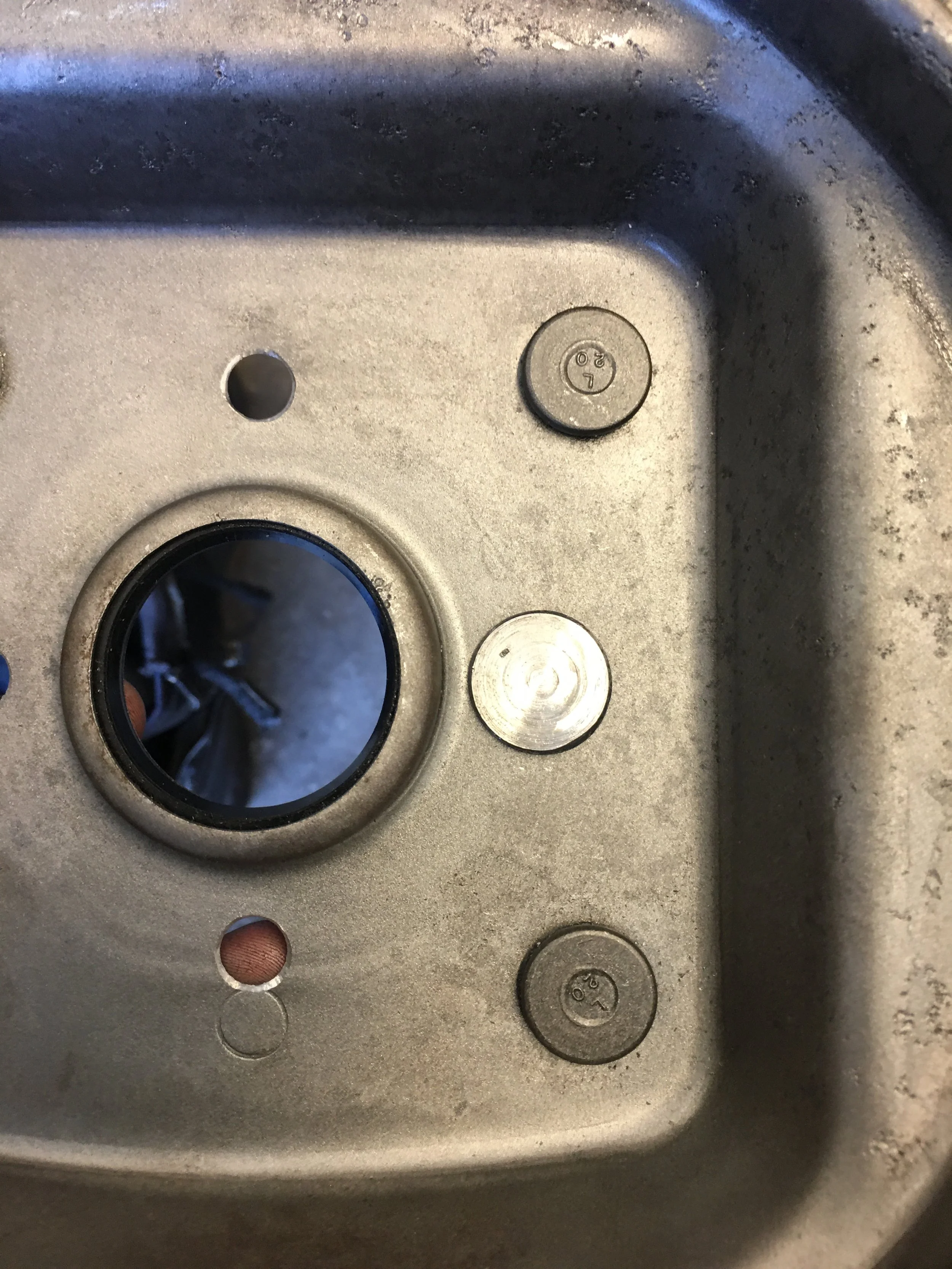
All of the brazing will take place on the inside of the case. This should leave a cleaner look on the outside.
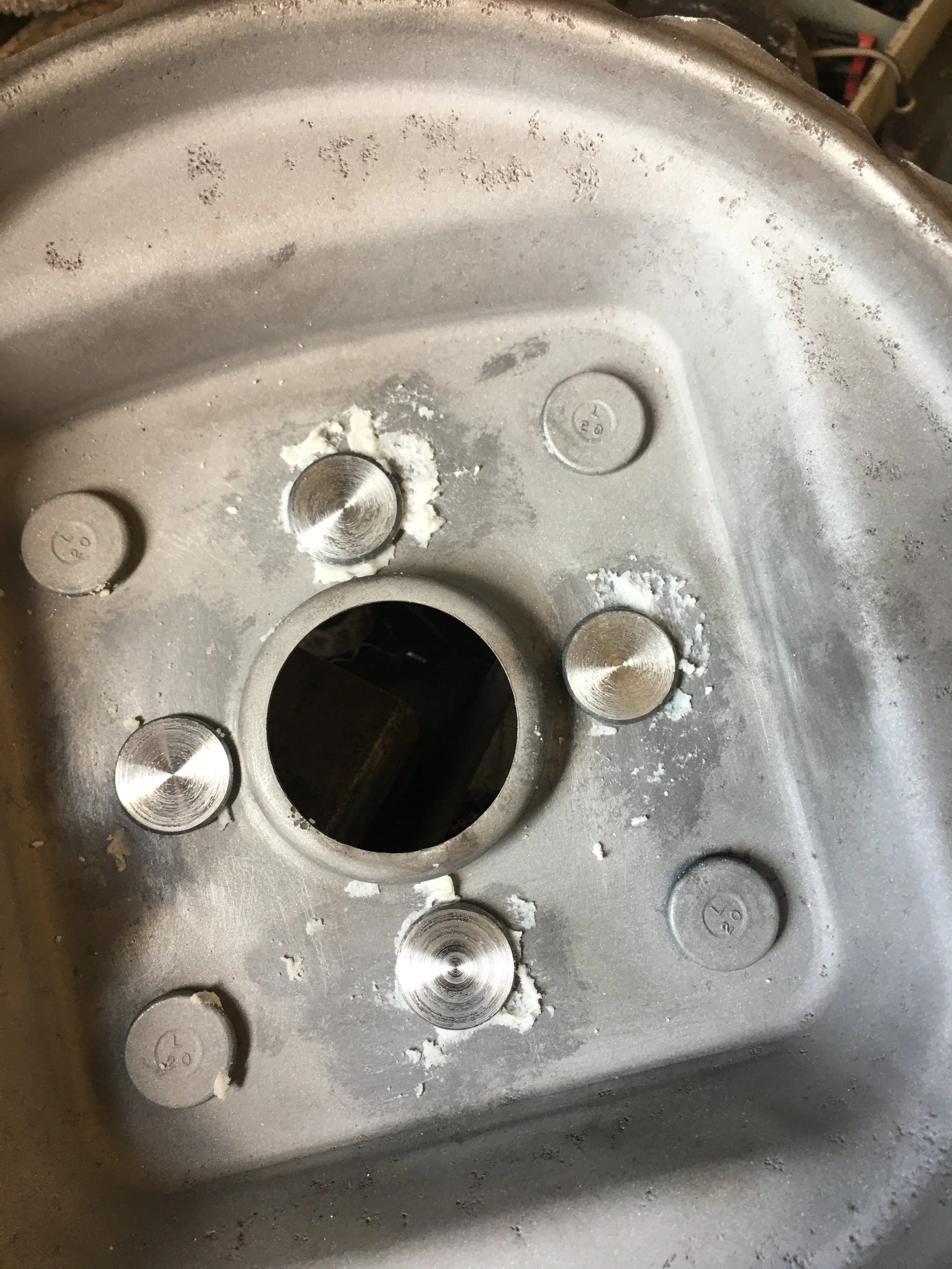
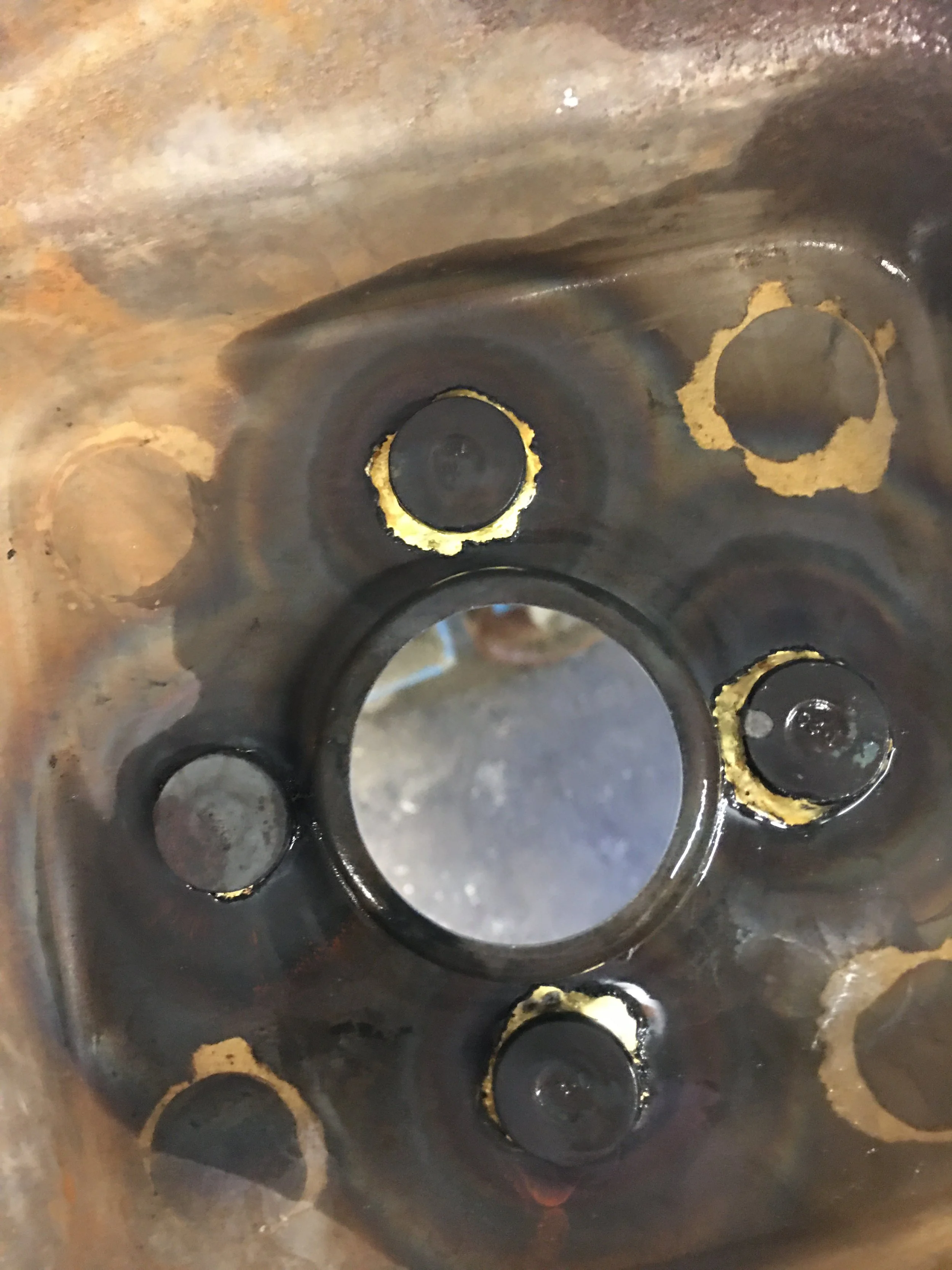
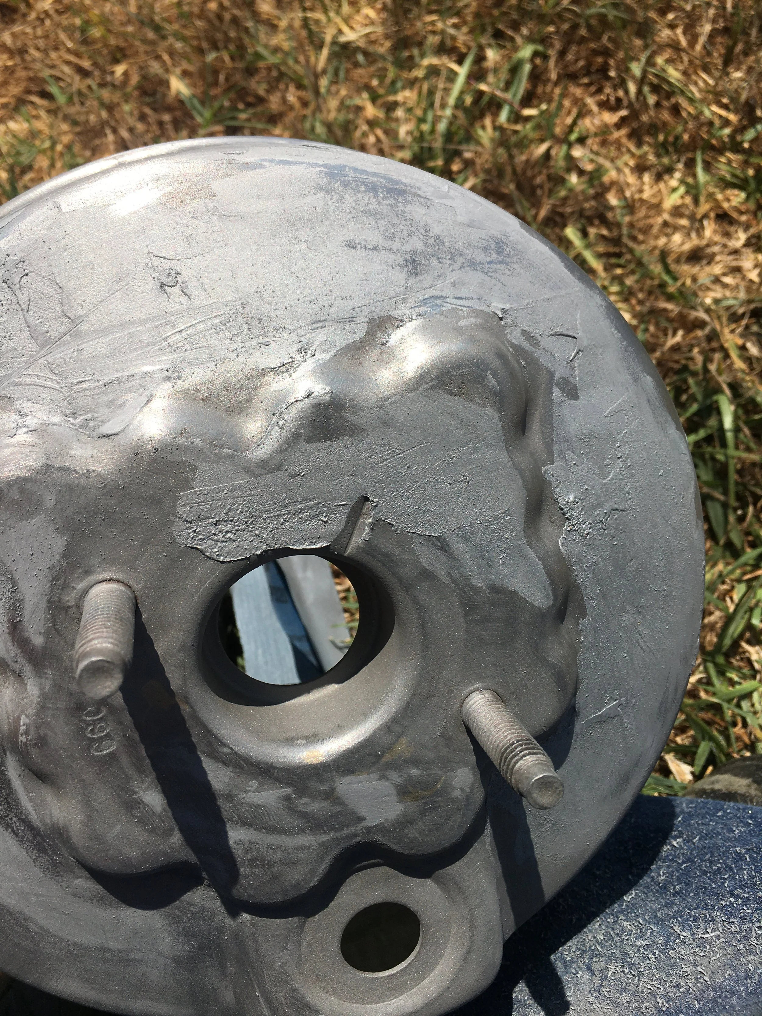
The shell was media blasted after all of the the brazing was done and the wedge was test fitted. The fit was snug but far better than the first booster plus there was no fear of disrupting any seams around the studs. There are no seams to disrupt.
Solid
Solid
Leaky
Leaky
One more operation before this booster can be declared finished.
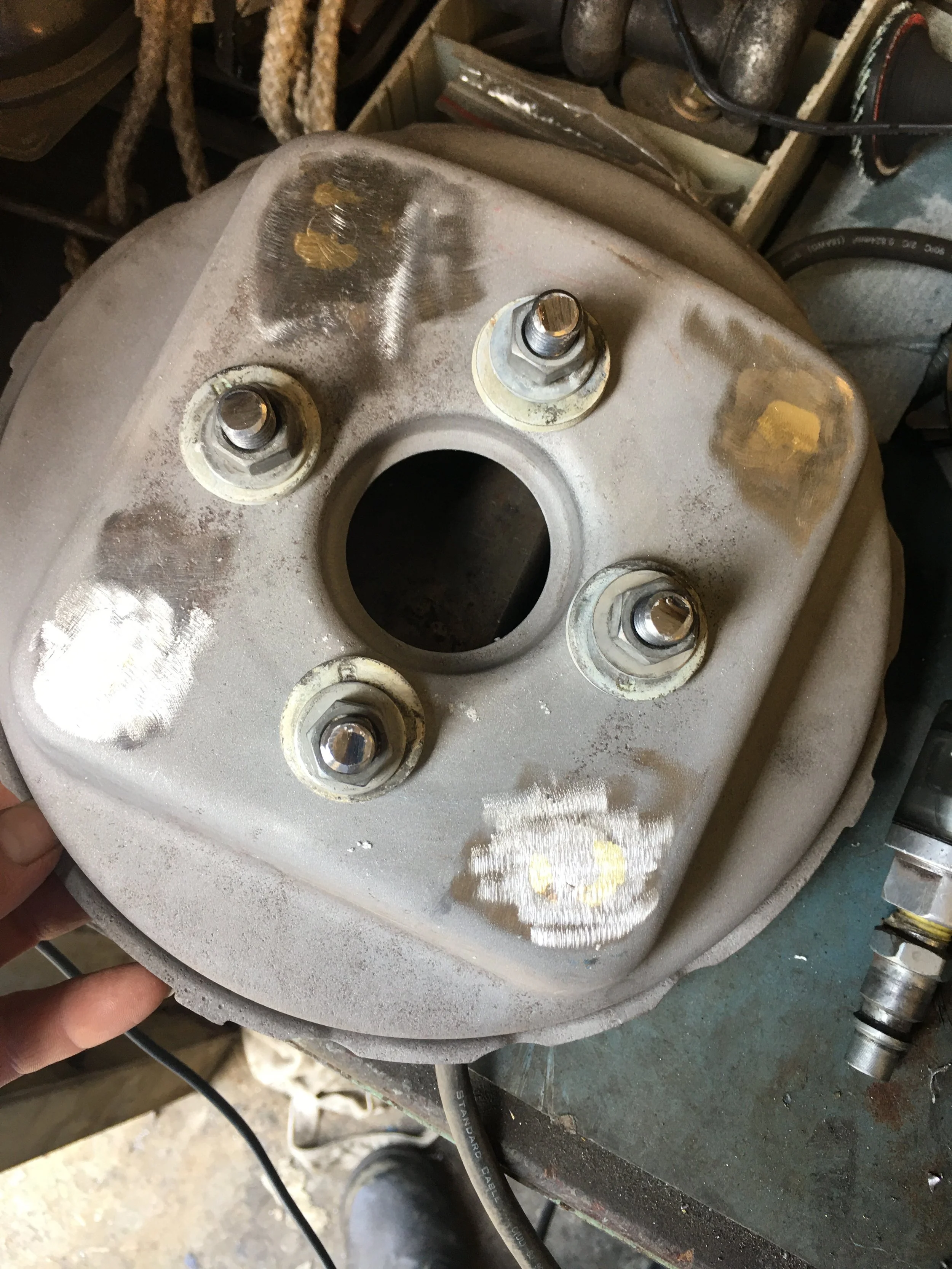
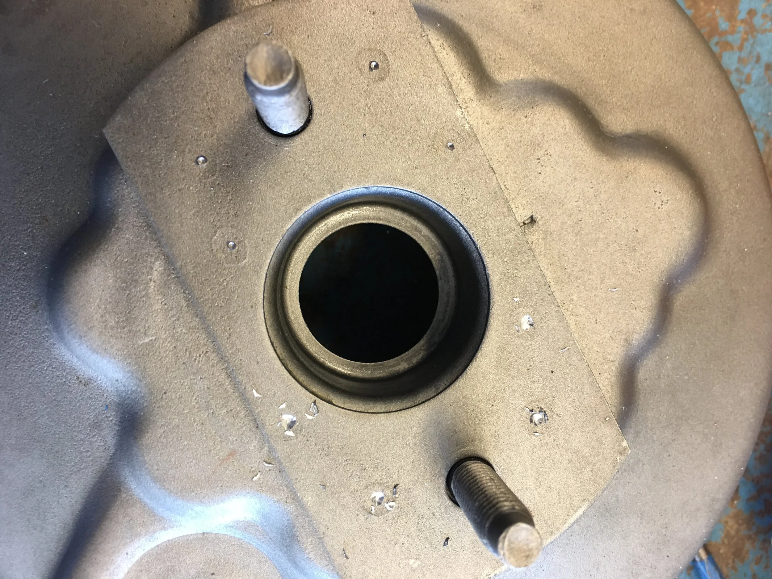
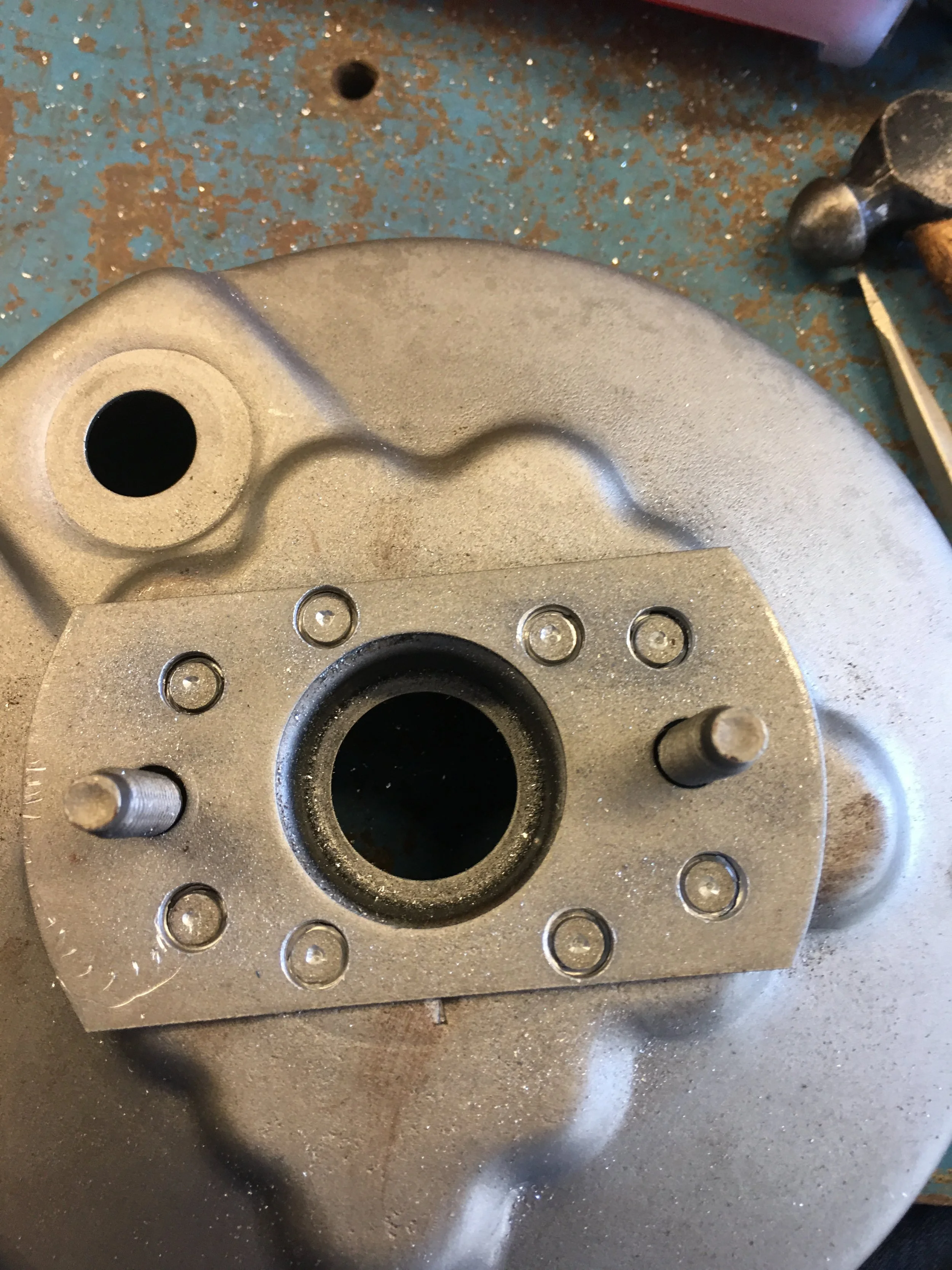
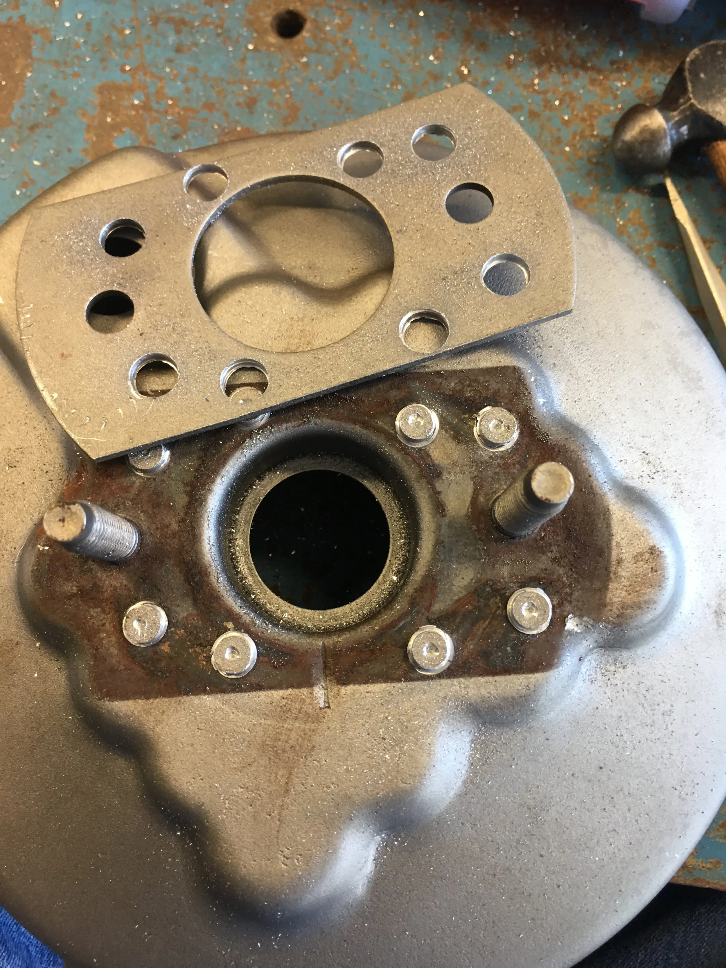
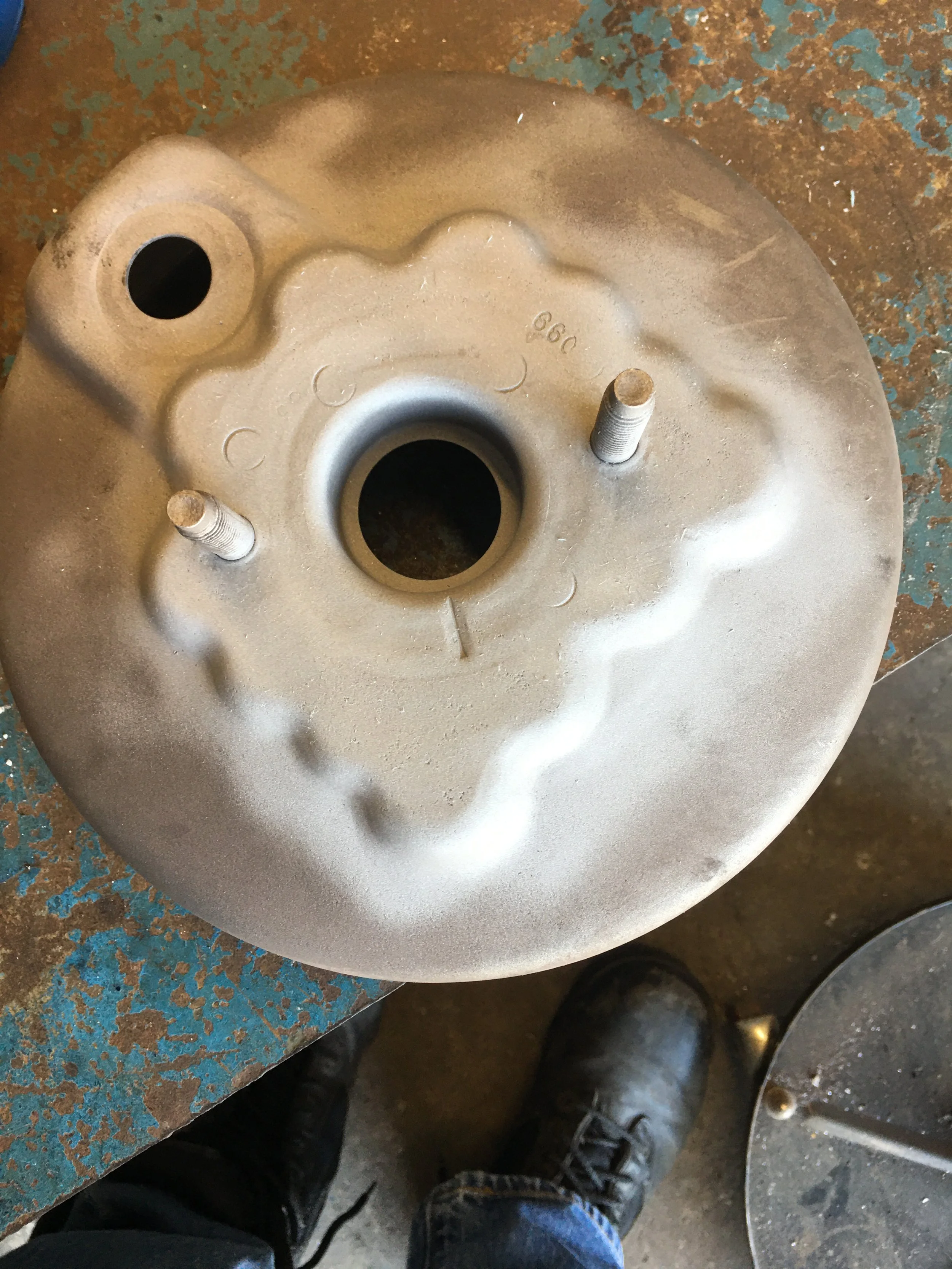
The Cardone 54-73512 vacuum booster for a 1968 to 74 F250 pick-up truck looks nearly identical to the the Boss 429 Booster except one glaring difference. The truck version has a plate across the front of it. I have no explanation for what this is for. In a discussion with myself, we felt there was no practical reason to have this in our application so we decided to remove it.
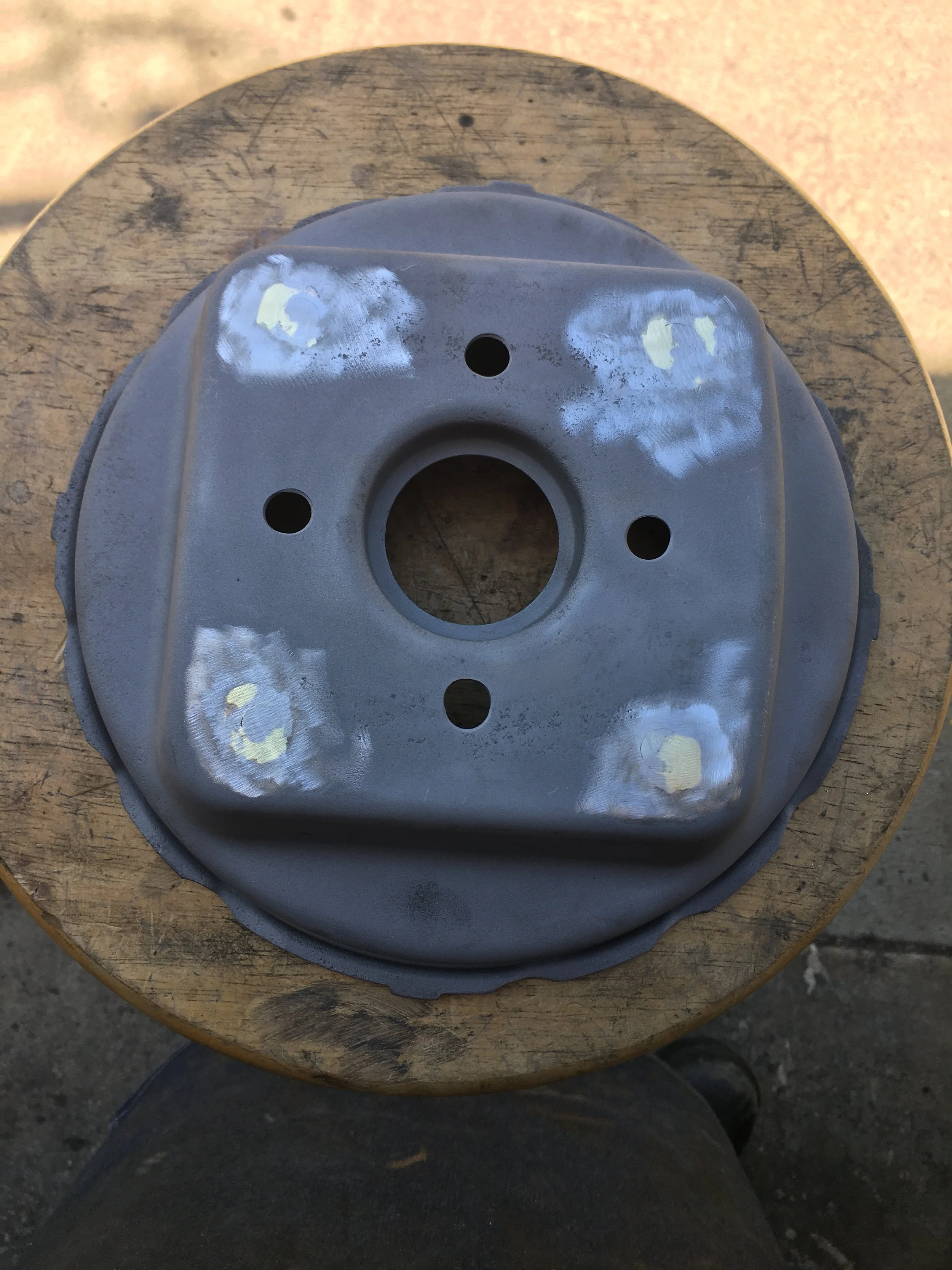
A little All-Metal filler and then a couple of coats of paint and the booster shell is finally finished.
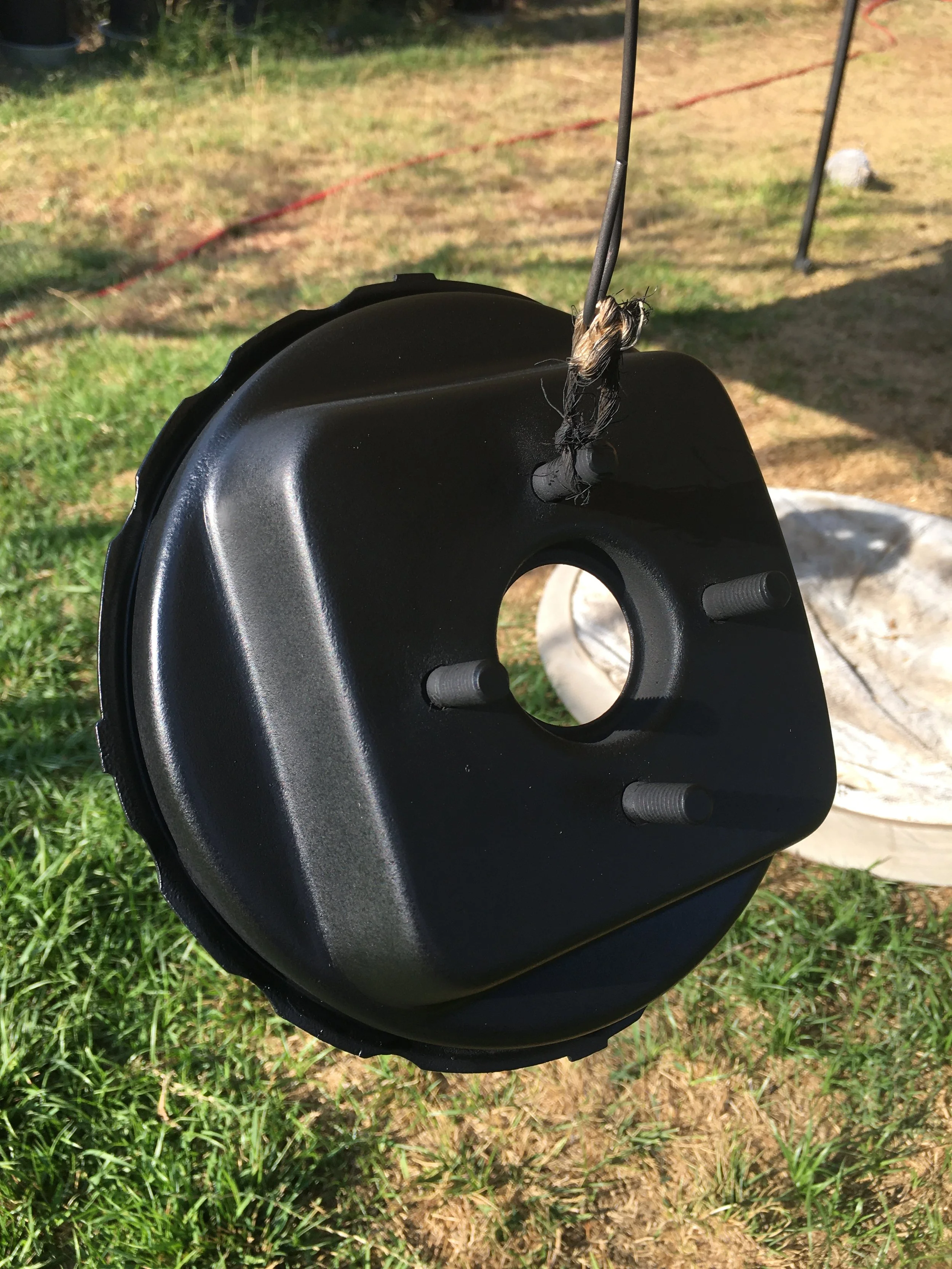
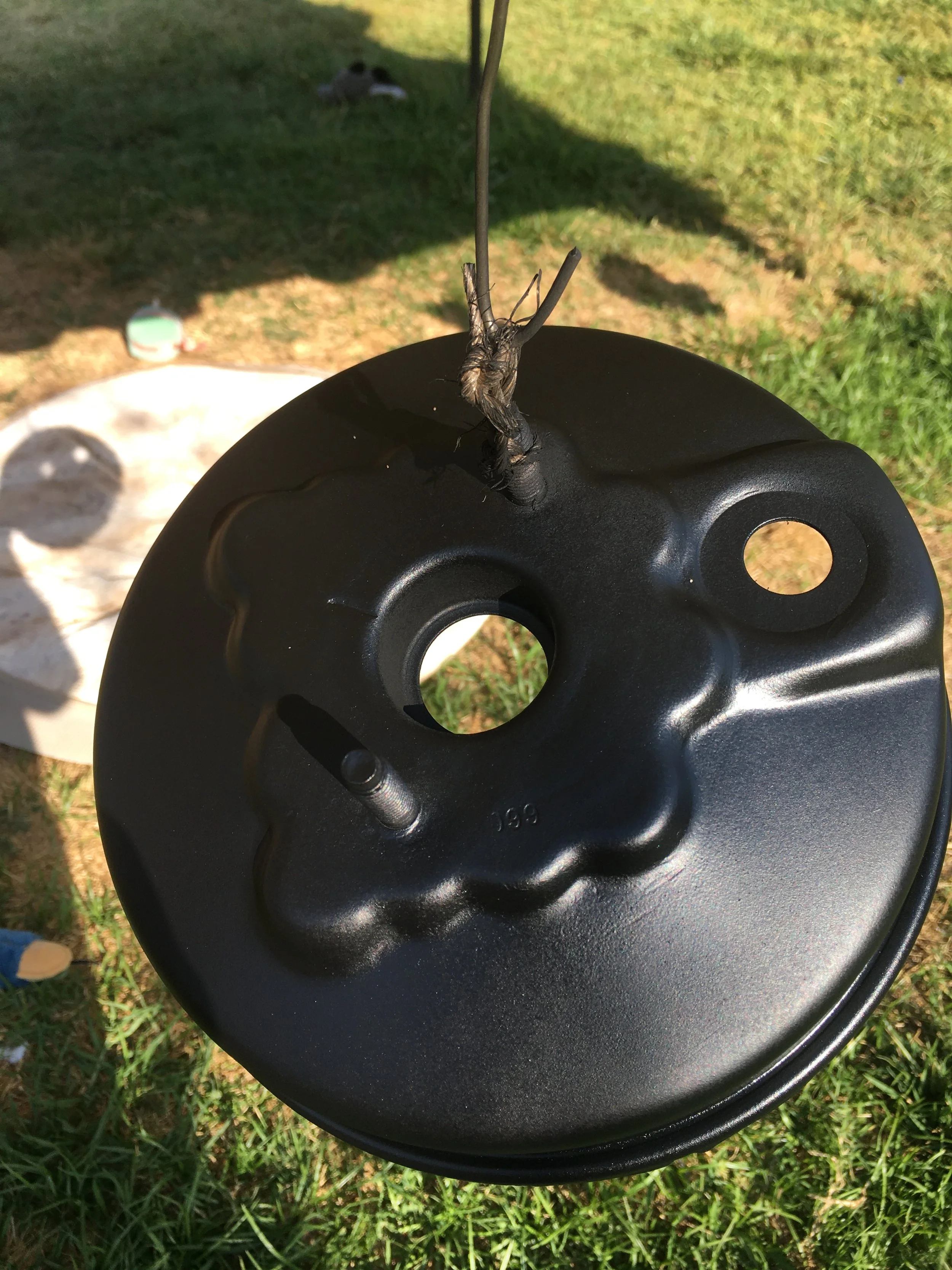
I painted both the inside and out to protect the booster shell against moisture build up and rust.
I made a back up booster to this one so I could have a spare. Most rebuild kits cost more than what I paid for a complete booster so why not?
The case is done but not the booster. Now it’s on to the push rod.