
Getting into my head
With the combination of burn out, wrecked back and work, I’ve been avoiding working on the car or any parts of it.
The pulley hunt doesn’t really count
The last section I was working on when I pretty much said, F@$% it, was the exhaust. I came to an impasse and walked away. I recently had the thought to correct some of the issues I had with the exhaust by modifying the transmission cross-member, the exhaust on the right side is rubbing up against it.

I’ve been wanting to get back to the engine. I think it’s time to put this thing together. The short block is assembled. I’ve done the steps and procedures to figure out the static compression ratio on the cast iron block and heads but since I’m going with a different set of heads and aluminum block, I figure it’s probably best to run those tests again.

I also have to upgrade the valve springs on the aluminum Robert Pond heads that will go on this engine. I decided to go with a slightly different camshaft from when I had the heads put together originally.
As I see it, I have three different projects to welcome me back to the Mustang build. I’m going with the valve spring swap first.

I really identify with Charlie Brown. Most of you should be familiar with the character. He’s a good kid who just happens to not have the best of luck. Despite his best efforts, things just seem to go wrong for him. Charlie Brown also likes red heads, I like red heads. This whole car has been one giant Charlie Brown experience and these heads are a good example.
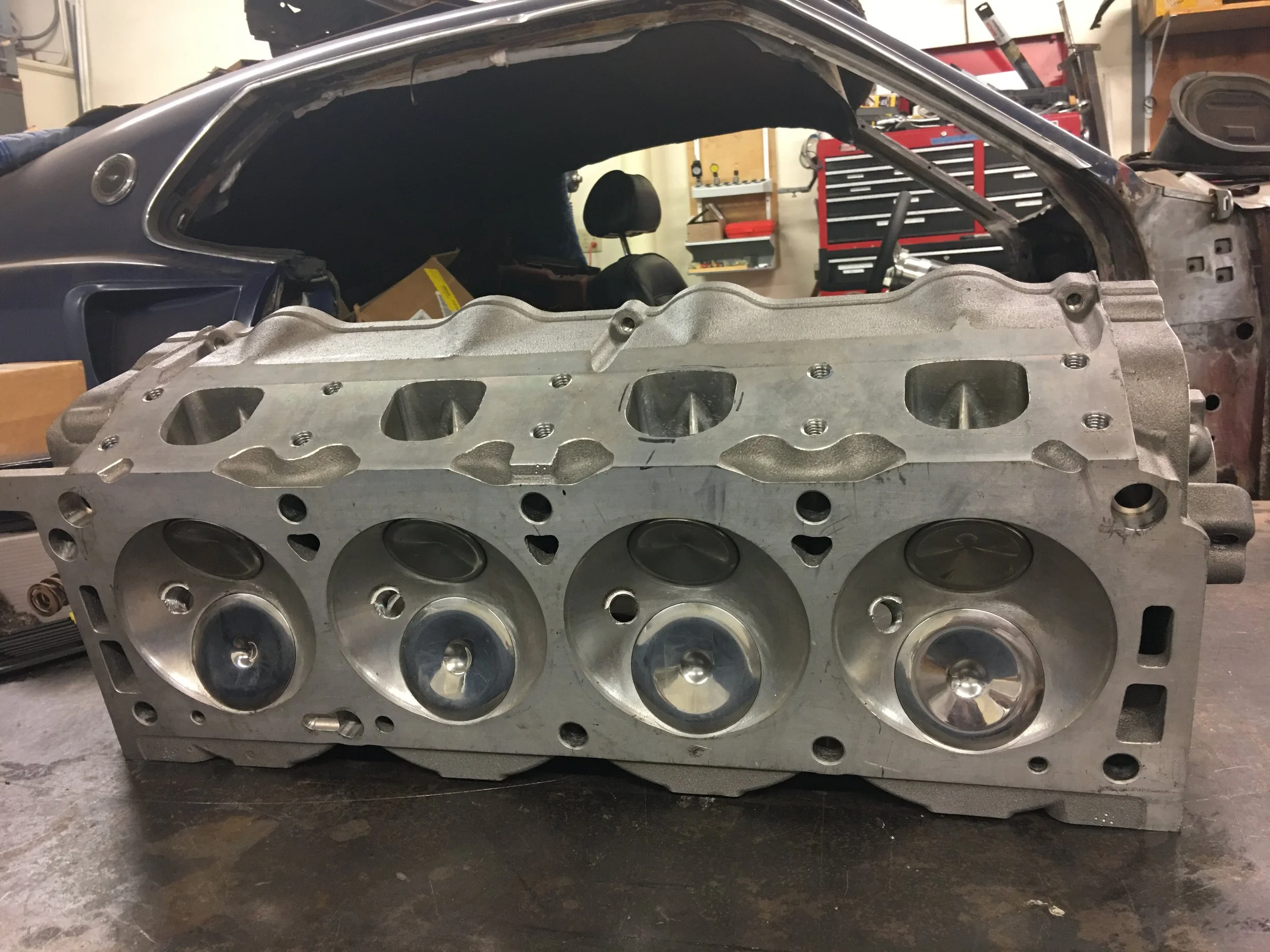
My butt is still dragging from working for a week and a half on the nightshift so I wasn’t overly productive when I got to the shop the other day. One cylinder head was sitting on the work bench and the rocker arm shaft and cam caps were off of the head, they need to be removed to make removing the springs easier. I’m talking to Kevin as he’s working on his Pathfinder. As we’re chatting I get curious about the oil passages through the head.
The oiling is pretty straight forward. There is an oil galley that runs the length of the head. It’s a straight through passage. The head gets its oil supply through a port in the block deck, this port intersects the cylinder head galley.
The galley supplies oil to the cam journals and rocker arm shafts

I get a piece of welding rod and start poking it through the oil passages. The passage from the deck to the galley is a clear shot. I can see the welding rod pop up in the galley when put into the supply port.


The passages that feed the two rocker arm shafts pass cleanly through to the galley as does the front cam journal oil supply port and that’s it. I poke the welding rod down the other cam journal oiling ports and they don’t pass through to the main oil galley.

Before pulling the diagram from above out to confirm this, I went to my cast iron Cammer heads and did the same test with the welding rod and on the cast iron head, every oil passage in the head comes from the main oil galley.
The answer is so obvious and what needs to be done to correct it but to be on the safe side, I decide to get ahold of Robert Pond and his affiliates to make sure they didn’t do any modifications to the stock oiling system and that what I am seeing is normal.
I get a reply to my inquiry the next day.
The deal with these specialty type manufactures is that they tend to keep inventory low. With something like cylinder heads, they will generally take orders and when they get enough of them, they will then make arrangements with their favorite foundry and have them create X amount of heads.
It would appear that other heads from this same batch have the same issue. I get the go ahead to finish what the machine shop fell short of. The oiling ports fall short by about an eighth of an inch.
I’d like to make a note here that Robert Pond works with a foundry to make his blocks, heads, intakes, etc and from there he sends them to a machine shop to do all of the machining. I didn’t want to draw any negative attention to the machine shop so I wanted to talk to them about the heads and that’s when I discovered that they are no longer in business. That’s when I decided to just contact Robert Pond.


Found that a .187 drill bit is the largest that would fit in the port. Nope, it still doesn’t go through even though I ignored it for 48 hours.


A few seconds of drilling and the bit popped out into the main oil galley. Thankfully Charlie Brown did nothing to mess this simple job up. Five journals per head drilled through with no issue. Brake cleaner sprayed through any and all ports leading to the main oil galley and even the galley itself. Compressed air blown through all openings to ensure no chips are left. The main galley itself is scraped to remove any displaced metal left over from the drilling process. I think the machine shop needed their drill bits sharpened because there was more flash left over from the holes they drilled compared to the ones I did.
Now with that finished, on to the main focus of this head work.

New valve springs!
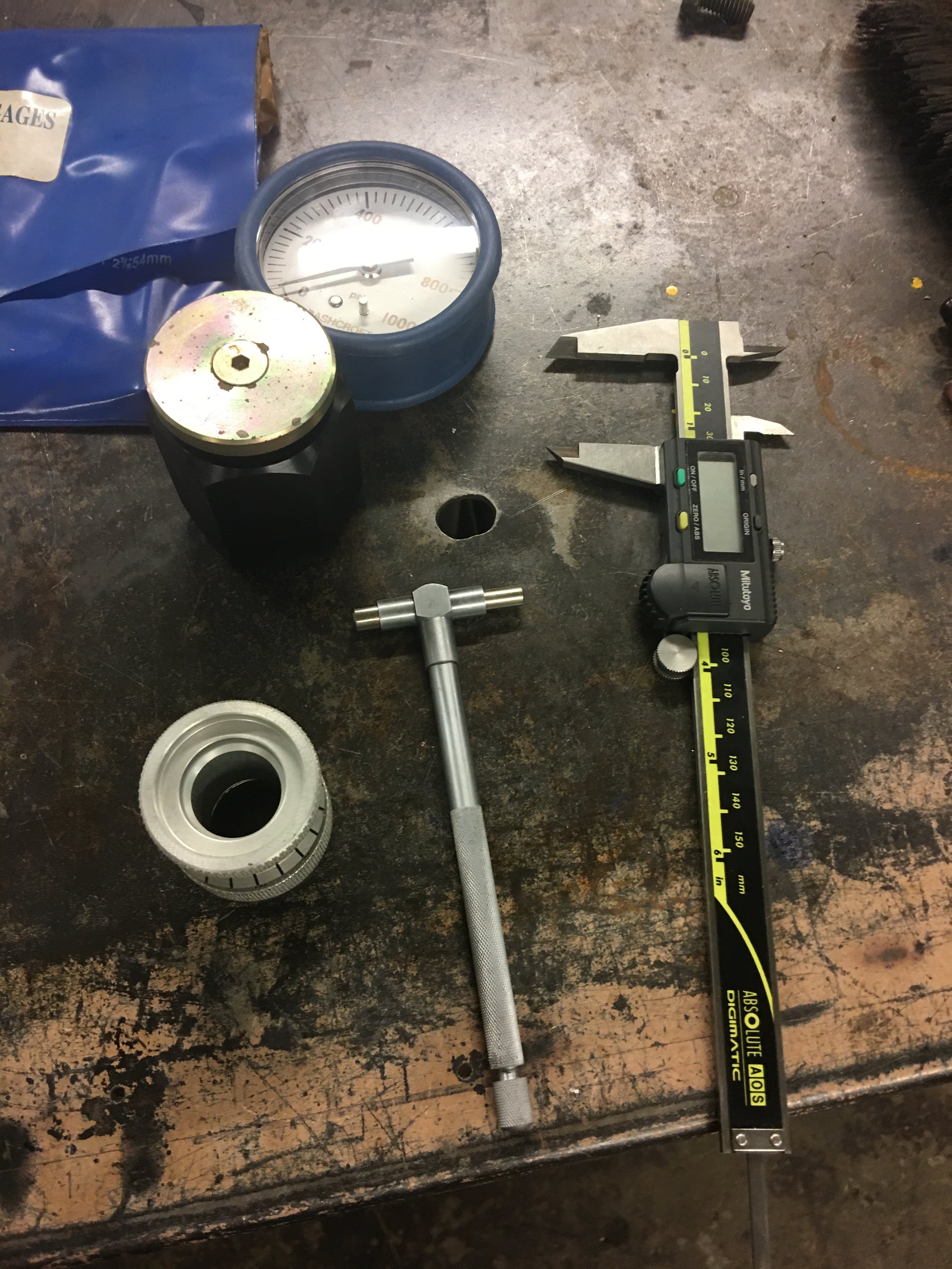


Some of the trinkets I’ll be using.
I’ve never checked valve springs before. One would think that since they’re new, you shouldn’t have to check the valve springs but that’s exactly what’s called for.
I have a couple of inexpensive valve pressure gauges. One has an analog face that goes from 0 to 1000 pounds. It works but I wanted something a bit more fine. I bought the second one just for this project. It’s a Proform unit and it reads from 0 to 700 pounds and it’s got a digital read out.
I bought an old used arbor press a few years ago in anticipation of this very job. I borrowed a plate from a hydraulic press to enlarge the arbor table and then marked its location in relation to the arbor and then made marks around the valve spring tester in hopes of keeping everything aligned with the arbor ram.


The procedure sounds simple enough.
Take a valve spring and put it on the spring tester. squeeze the spring using the arbor ram.
There are two measurements that have to be made. One is for installed height which, in this case, calls for a space of 1.9 inches. This is how tall the spring should sit when installed and the valve is closed. According to the spring box, the spring pressure at 1.9 inches is 240 pounds. The next measurement is with the spring compressed to 1.25 inches and this is called the open seat pressure or when the valve is open. The spring pressure should be at 598 pounds.
What I’ve read is that the springs don’t always exhibit the proper pressure at the given heights. To make up for this deficiency, round shims are required and of course they don’t come with the springs. They’re extra. Comp cams offers a shim kit that consists of three different thicknesses. .060, .030 and .015. I don’t remember how many per.


I use oversized washers. One thick one on the base of the spring checker and a thinner one on the spring itself. I need these to ensure a proper way to check the actual height of the compressed spring.
I didn’t think I’d be using the shims but by the third test, I was proven wrong. The third spring could not compress the spring to the required pressure in the space allotted for it. This happened with the majority of the springs. Most of them required a .030 shim.

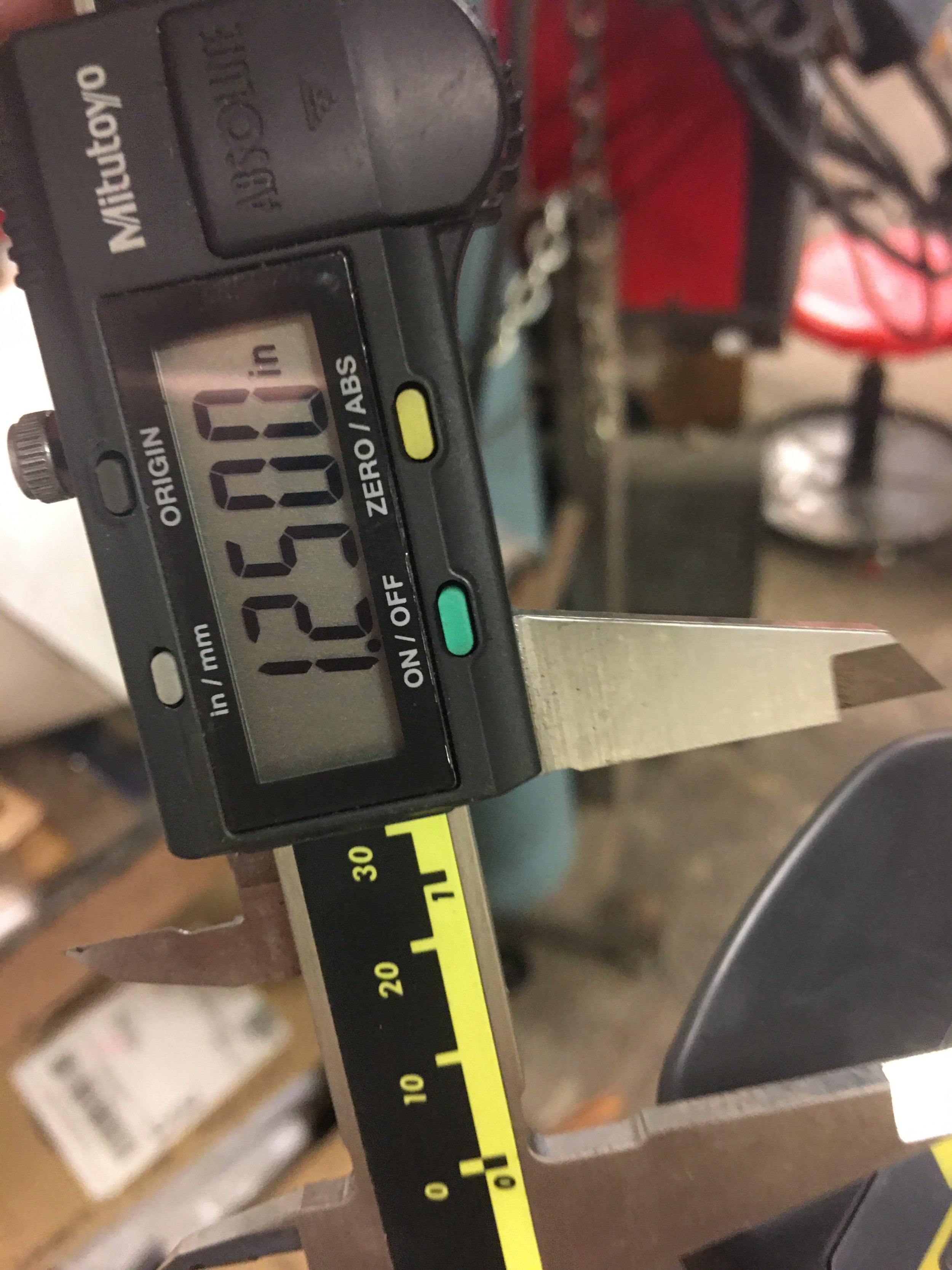

Even though I had a telescoping gauge set up, it didn’t prove all that effective in the environment I was working. It was too fat to fit in the space I had to work with. This slowed me down. I was hoping to check each springs installed height and open pressure by using two different gauges set to the appropriate settings. Since the telescoping gauge wasn’t working out, I was relegated to the vernier calipers only. I ended up checking the installed pressure on half of the springs first and then went back and rechecked these same springs at their open pressure.

When I had checked all of the springs, the ones that required shims had safety wire around the shim and a coil of the spring to keep them together.
It was pretty late by the time I finished this step so I called it a night