
Joseph P. Header. Esq.: Fini
I’ve already documented the ins and outs of header design selection and that nearly drove me crazy reliving that. So, in order to, hopefully, wind up this nightmare of reliving the header build details, I’ll talk a bit about the actual pipe routing in plastic and then transferring that shape to metal.
I’ve never tried the ICEngine modelling blocks for header design so I can’t tell you how they fit together.
I made three different sets. One was a design I found on Thingiverse, a site where people share 3D programs and designs for machining and 3D printers. The other two were of my own design. I would make another set if I were going to do this again. I’d use a different filament and make one or two design changes.

Starting with this flange on the left side, I felt this would be the tougher of the two. These anchors would change a few times before I stumbled upon the combination that showed the most promise.

From 4 into 1 to 180 degree to a Tri-Y design, every design looked like this starting out. No matter what the back half was doing, the top section had the same obstacles.
Because the filament I used was pretty inflexible I couldn’t get the fit right. Either the pieces fit ok, too loose, or too tight. It wasn’t consistent. The longer the pipe got, the more inconsistent it became so I took to using masking tape to keep the pieces from rotating. The modelling parts held together okay, they would just spin at times. I actually preferred the joints to be loose. With no space to work with, it was difficult to get the pipe to angle in just the right place. Sometimes the wrong piece would turn, which would throw the pipe shape off. Besides masking tape, black Sharpy pen was a huge help. The modelling pieces had a marker set every 30 degrees apart around the circumference of each end.

All of these gadgets helped out when it came time to recreate the plastic exhaust into metal.


This is the right header, I didn’t take pictures of the left. I wish I had, it looked pretty cool prior to taking it apart.


Number 5 cylinder, first pipe on the left side. The pipes are tack welded. Using the plastic pipes as a guide, All of the pieces are cut to size before assembly begins. I use a jig to put reference marks on the end of each pipe similar to the markings on the plastic modelling pieces.


Right side header. I have a spare flange so I can leave the test rig together to do a side by side as the header is built. I get thrown when looking at these pictures sometimes. Instead of focusing on the OD, my eye gets drawn to the openings and with the plastic having that hole for interconnecting the blocks, I keep asking myself why the test pipes look so small.


Shot of the left side 4 into 2. The pic on the left is how the pipes were designed in the car while lying on my back. After they were tacked together and I could see them in steel I didn’t like the way the #6 exhaust primary had those extra twists and turns. I didn’t like it from a build aspect and an aesthetic one.
The picture on the right has the #6 pipe with a cleaner straight shot to the collector. Of course there was a lot of test fitting and adjusting before it was all tacked into place.
No, there are no equal length pipes on this bitch. If there are rules to building the Tri-Y headers, I completely ignored them in my quest to just get the pipes to carry exhaust gases to the back of the car.

This was a few months ago and one header still has the first 2 into 1 collectors uncut and the other is ready to go.
At this stage there is no longer a need for the modelling blocks. There are still a few rough spots to get by in the car.
A big challenge was trying to find pipes with a consistent diameter in the bends. For the 2” OD 2” CLR, I had the metal donuts. These matched the Od of most of the straight pipes I used. It’s when I needed the 2” OD 3” CLR that I began to have problems.
I used at least four different pipe manufacturers and I got lucky only once with a couple of U-bend pipes that worked for me. I needed U bends that had an OD of 1.97” at the very least. I had a couple of U bend pipes that were in the desired range. The rest were down around 1.92 to 1.94. All of the pipes were mandrel bent but there was no controlling how much the pipe was stretched when it was bent. The more they stretched, the thinner the OD at the bend.
That doesn’t sound like that big a deal until you try to match the pipes face to face and that offset of the 1.97 to 1.92 is huge. The difference affects how the pieces weld together.
I was finished with the Primaries when I found out about Pie cut pieces for the bends. Using those would have saved me a lot of work.
I learned how to Tig weld while building these headers. I hadn’t really done much Mig welding until 2019 when I started on this car so I can’t really say that pipe selection would have played that big a part in fusing the pipes together if I had more experience with welding.
If anyone thinks that they would like to weld on a piece of pipe and then expand it at the weld, let me give you a bit of advice. Either gas weld the seam or Tig it. Although Mig is easier, it has a tendency to make the metal around the weld harder. Its arc is very hot.
WTF is he talking about?
The donuts I used are from a company called Deez Performance. The donuts are beautiful. They are made from two metal circles welded together. Think of it as cutting a pipe in half lengthwise.

The outside diameter of the donut is welded and ground clean but the inside diameter is not welded. This will have to be welded shut before it can be used.
My first attempt was to cut a section of pipe out and then Mig weld the seam. This worked except I tended to melt the edge and leave an indentation on the seam edge. After cleaning up the bead, I would find that I was a bit too aggressive with the grinding and the metal was thinned. Both of these are surmountable issues, I just have to be careful when joining this piece with another one. The big issue presented itself when I tried to expand the end using my super fancy plug on the heavy duty press.

The metal would stretch a little but eventually it would split around the weld. It didn’t always split at the seam. Sometimes it would split right next to it.

After reading about the Mig being too harsh on the metal, I tried using the gas welder. I was real surprised when the seam held when stretching the metal. I was still having the issue with melting the edge of the seam but again, not earth shattering.
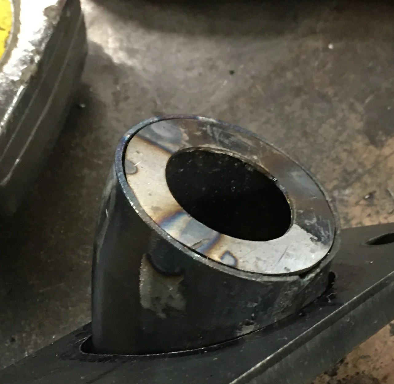
Not totally obvious here but you can see a divot at the top of the shorter pipe edge. Yep, bad welding skills.
Eventually I hiked my pants up and Girded my loins for battle and decided to try my hand at the Tig welder. By now I felt there was no reason NOT to weld the donut before it was sectioned. I’d been practicing fusion welding so that’s what I did on this donut seam. This worked well because it left a fairly low bead. Cut a section out, welded on a 3/8 wide ring to one end and then formed it into a D shape and then expanded that end. All of the seams held.


I couldn’t get a Mig weld to not break when I stretched the metal. I am not saying that it can’t be done. I’m sure there are plenty of people that have the skills to do this. I’m just not one of them.
Just a little warning: You can find these metal donuts on ebay. They’re about half the price of the Deez donuts but they are crap. The welds are weak and the finish is horrible. I did find that Summit offers donuts and they’re pretty good. I went with Summit for one donut because it was 2 1/2 OD on a 2” CLR. Everyone else who had a donut that was made of a 2 1/2 OD pipe only offered 2 1/2” OD on a 2 1/2” CLR.
Ok!, Between this drawn out story and the earlier posts declaring that the Headers Are Done!, I think that covers the build of the headers. I mentioned before that I plan to get these things ceramic coated, probably somewhere local. I’ll update ya’ll when that happens.