
Joe Mama’s Header: OMG, it’s part 7
Big Sigh! Writing this out is almost like reliving the build all over again except I’m not freezing in the shop or inhaling small particles of metal dust.
I made some special header modelling parts that can be bolted to the flange. They’re really anchors if I have to put a name to them. These will act as fill ins for the starter pipes while the headers are being sorted using the plastic modelling pieces.

Three examples of the anchors made on the 3D printer. Blue is 2” diameter with a 2” CRL. Orange is 3” CRL, the black is a 1/2” straight anchor and the far one, well, that one is unique.
The 3D printed anchors are held in place with a 5/16 bolt and of course the bolt needs something to screw into. Somewhere I dug up some 1/4” X 1” bar stock and cut 8 pieces about 2” long. Each tab had to be ground a bit on a belt sander to shape them to their ports. Once all eight were fitted, each one was tacked in from the back to temporarily hold them into place. I tried to make sure that the face of the tabs were flush to the face of the flange


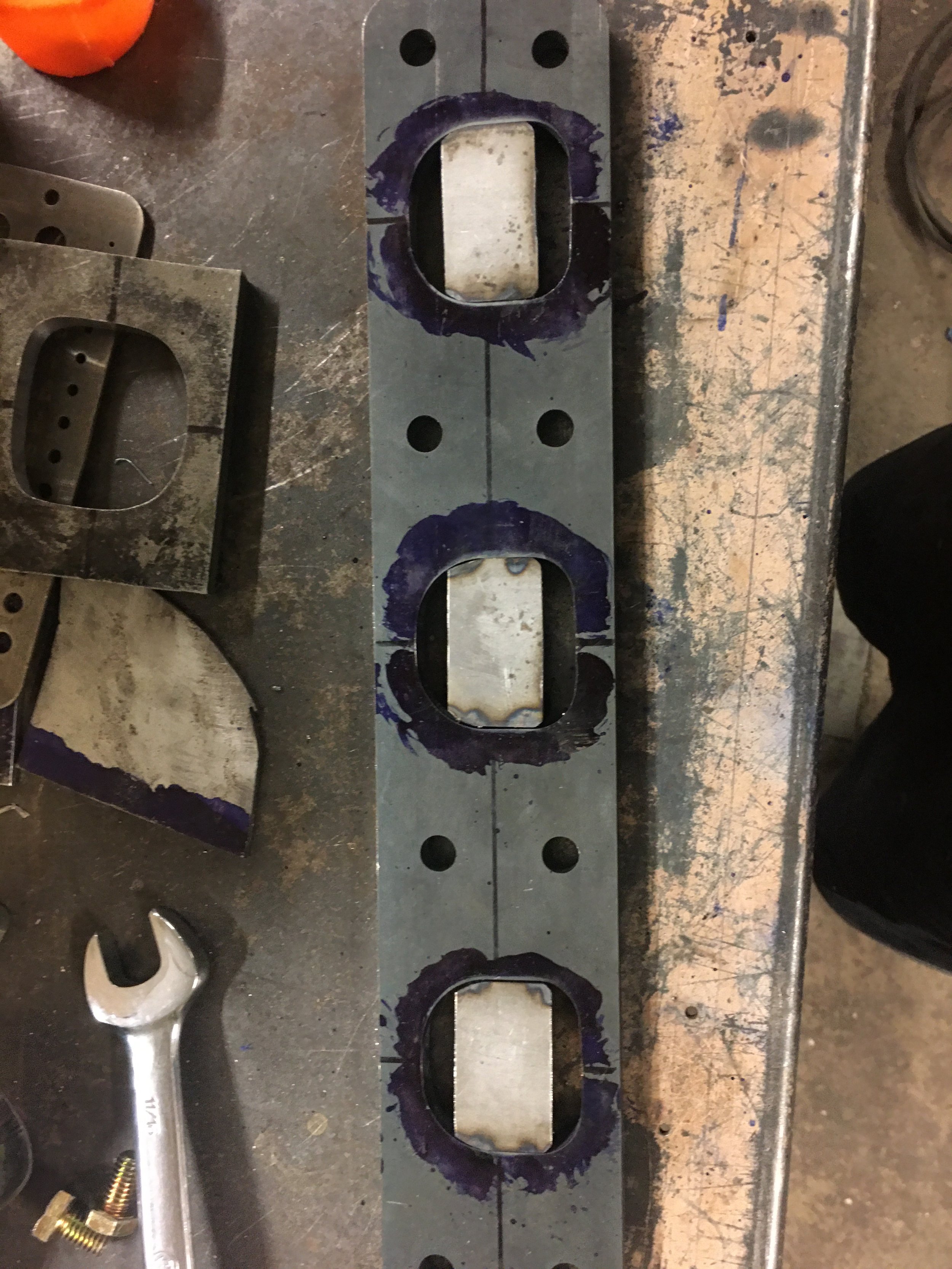

The idea is to have the anchors mount onto the flange so they approximate, as close as possible, to how the starter pipes will weld in. Using a combination of the enlarged port template and a straight piece of pipe that has been expanded on one side, I was able to come up with a way to locate the bolt holes on the tabs so that the plastic anchors were located exactly where the actual starter tubes would be.


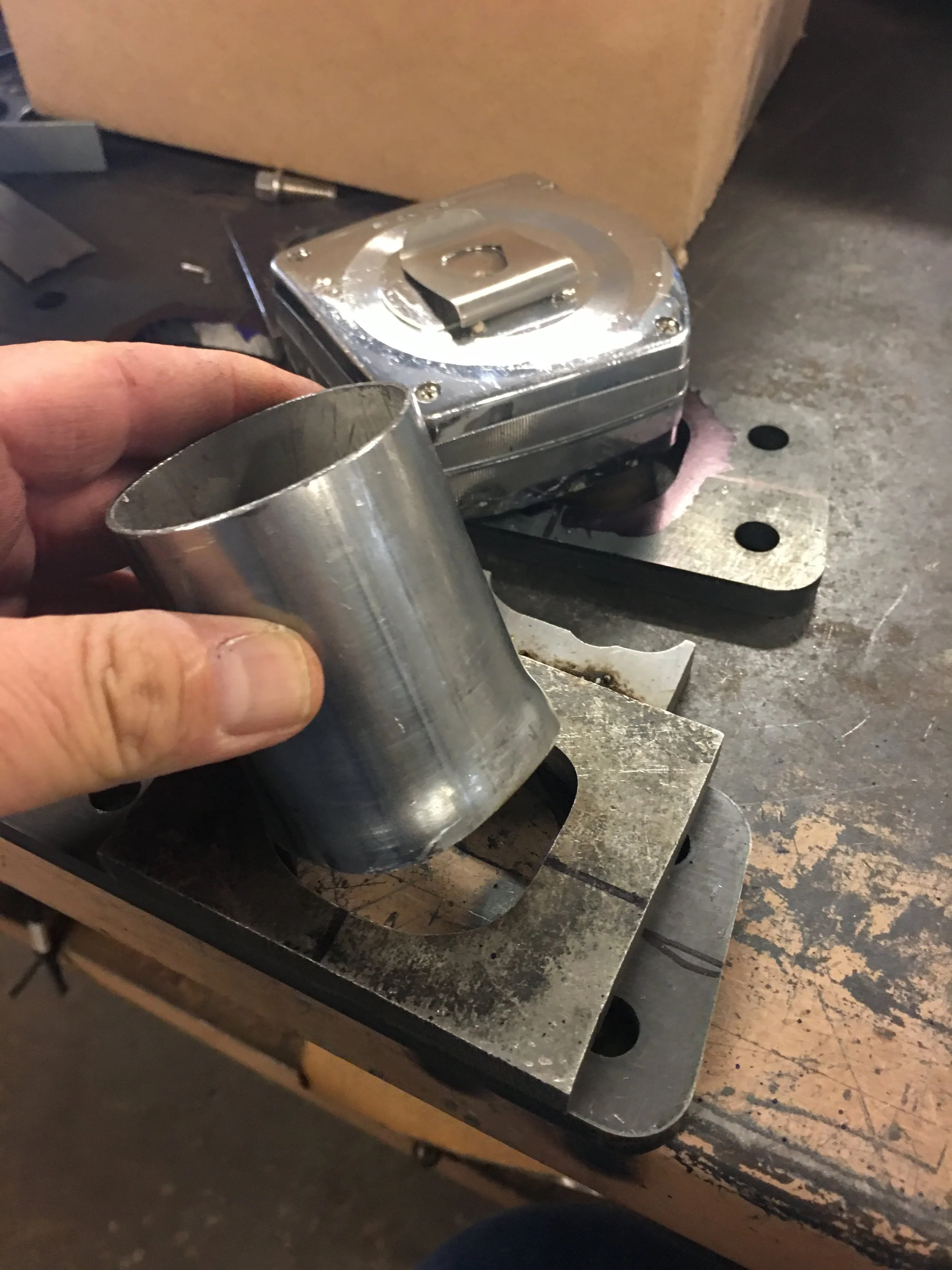


Using a trusty hole saw, a hole was drilled through a thick piece of lumber just so I could get the plug that remains inside of the hole saw. Not only will it fit snuggly into the straight pipe with the flared end but the wooden plug has a perfectly centered hole made by the hole saw pilot drill bit. A centering punch fits cleanly through the pilot hole and a witness mark can be made on the mounting tab.


With the tab marked, the tab can be drilled and tapped and with any hope, the anchors can be bolted onto the flange.
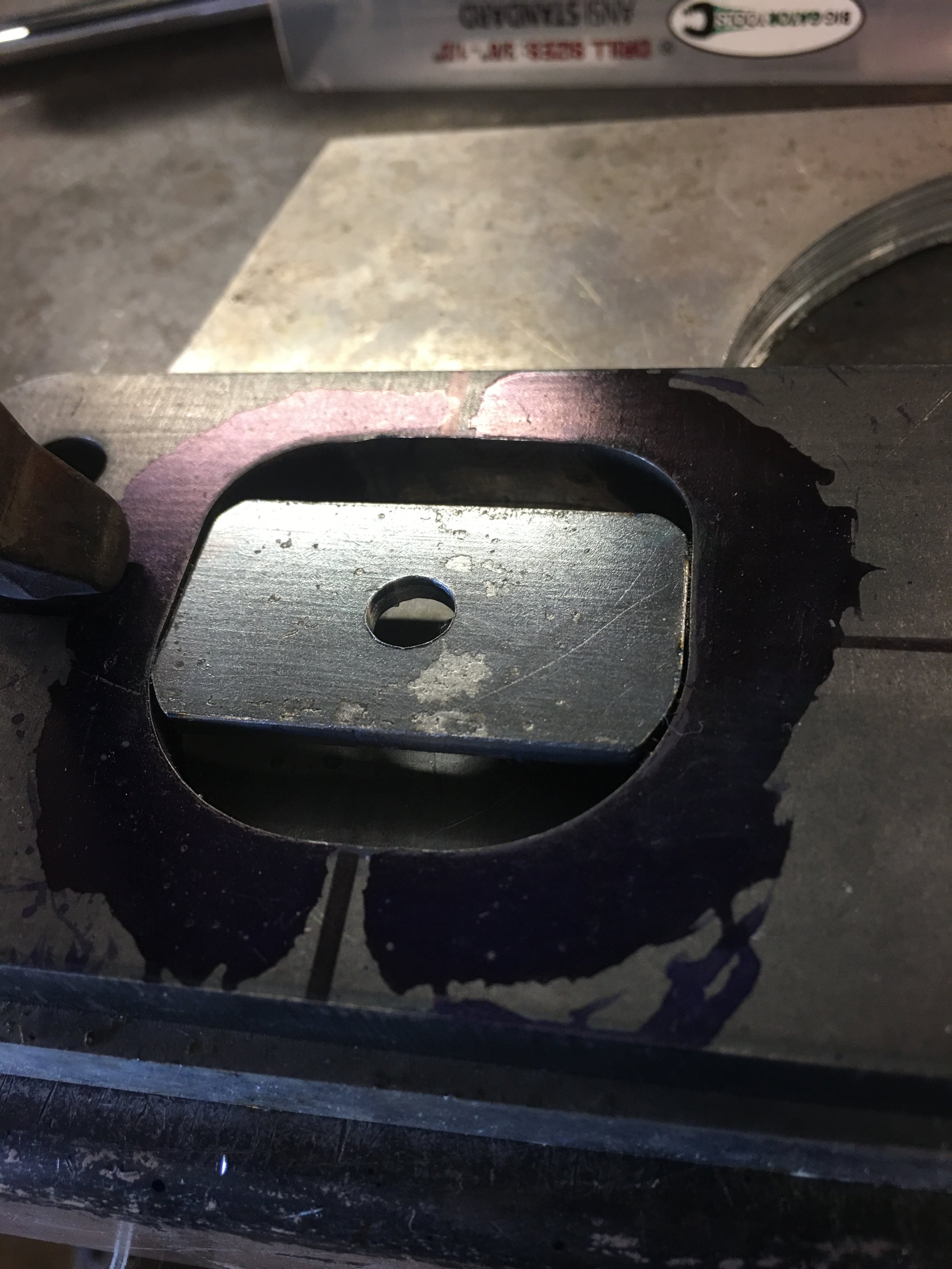


All eight holes were tabbed, drilled and tapped and then what I expected to happen, happened.

The lump dominating the lower left center of the picture is the steering box. As close as you think it is to the rear exhaust port, it’s probably closer. For those keeping track, that’s the number 8 exhaust port.
When the anchors were bolted on, the flange would not fit with the #8 anchor attached. The anchor kept hitting the steering gear. I could not bolt the flange into place.
At a 2 inch CRL, I don’t think I could have found a 2” pipe with a tighter bend than that. The anchor pieces, even the metal flange adapters sat on the surface of the flange. If I called for a 45 degree 2” OD. 2” CRL curved pipe for the flange adapter, that measurement would start at the face of the flange. In order to make this happen, a 3/8” ring is added to the 45 degree curved pipe so the ring is the section that is inserted into the flange. The ring adds stability to the pipe and it provides a surface to weld the pipe to the flange from the inside.


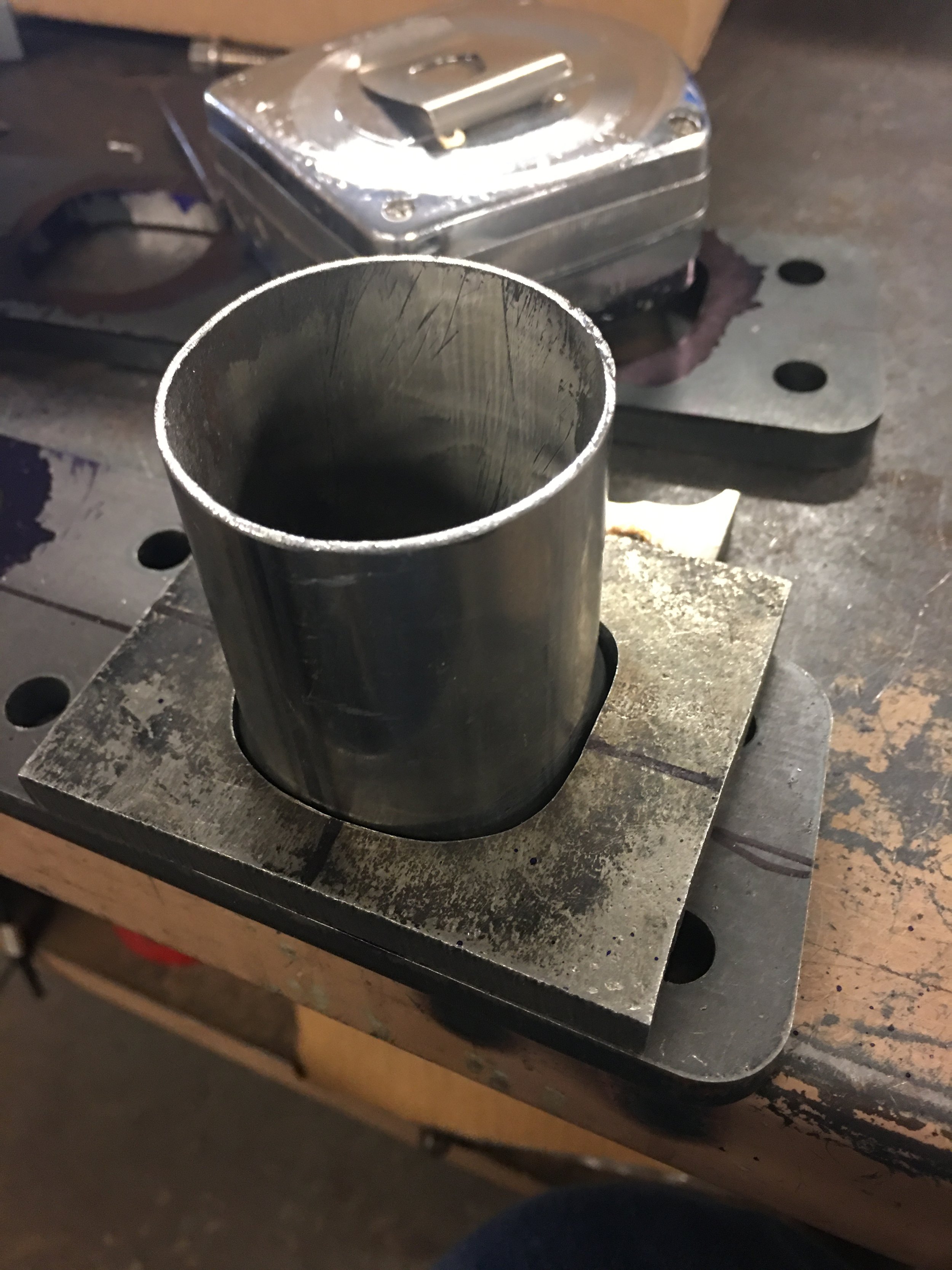
Instead of adding the ring to the adapter, a non-modified Arc was expanded. The flange port opening had to be relieved because the inside radius of the pipe was getting caught and not allowing the starter pipe from seating all the way in. A couple of tack welds to hold the pipe in place and the flange was test fitted. This time the bolts lined up. That’s a good sign.


Even with the starter pipe sunk in by 3/8”, the fit is waaaay close. I have concerns for how the heat will affect the steering gear grease but outside of changing to rack and pinion, there isn’t a lot more I can do.


A large washer was added to the mouth of the steel starter pipe so the header modelling pieces would have something to fasten to.
With that one washer tacked into place, the job of actually routing the pipes to make a header can now begin.