
Joe Header: #3. Is it soup yet?
We are so far from being soup. We’re just tilling the soil in order to plant the seeds to grow the ingredients to start the soup.


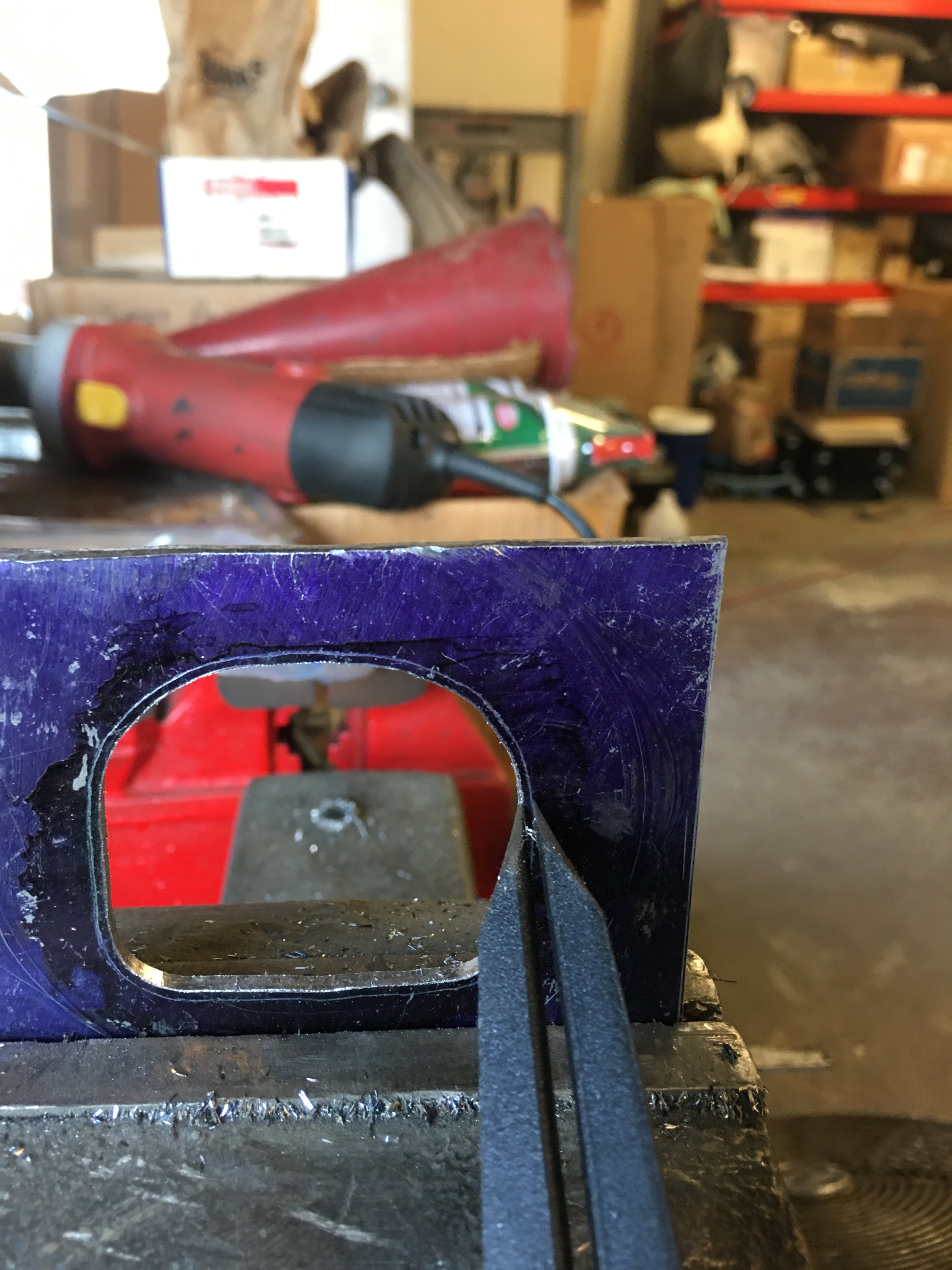
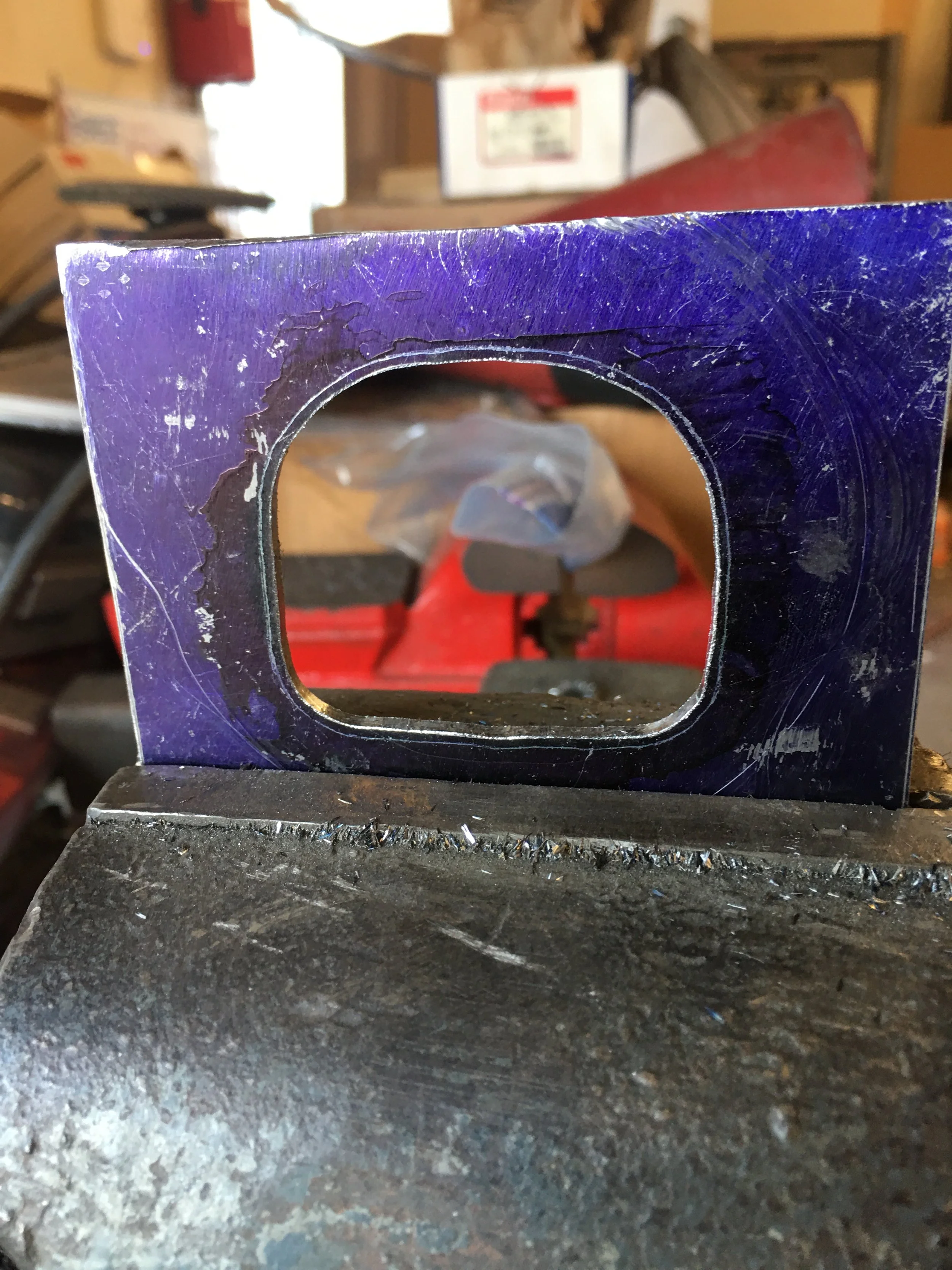
I made another template out of a 1/8” steel plate scrap. The plate was coated in Blue Dykem then the flange was plopped on top of the plate and the port shape was traced out on it using a metal scribe.
Like I said, I have holesaws and a die grinder instead of a CNC mill, they all get the work done, just depends on how hung up you wanna get on pretty.
With the template cut to shape, a line was traced along the outside of the opening with a machinist’s compass. I wanted to make the opening larger but I wanted to sneak up on it.
Trim the marked area and then lay it over the exhaust port to check the size. Mark, trim, repeat until I’m worried I went too far and then do it one more time. Now I’m definite I went too far.
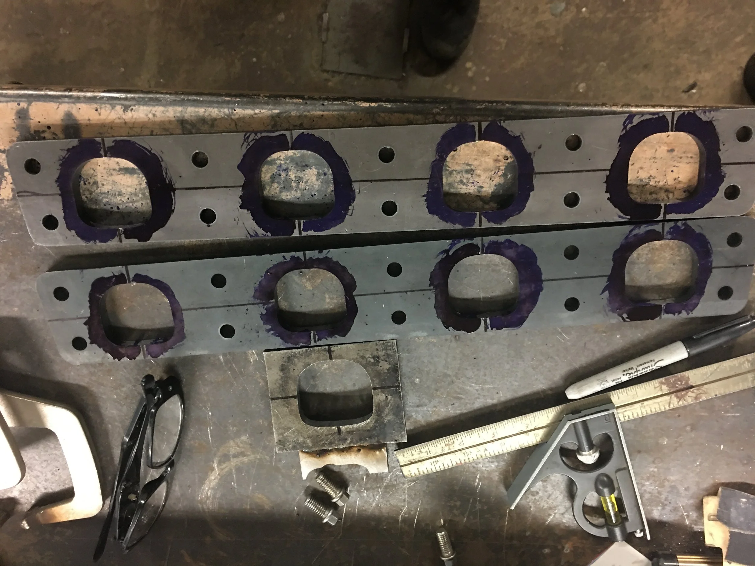
The next step was to transfer this improved port size to something thicker to make a jig in hopes of keeping the ports of the flanges centered up on their present location.


I’ll share a little something here. See the jig on the right? That opening got a little bigger and it wasn’t a planned modification and I’ll talk about the why later on.
Errr, ummm, now what? Yeah, I need to make a way to ensure that the jig comes close to locating the enlarged hole properly on the flange.

Not wanting to take anything for granted, I was hoping that I could find solid reference points to ensure that the exhaust port center point is the actual exhaust port center.
Not knowing what I was really looking for, it turns out that the spacing of the exhaust manifold mounting bolts are pretty uniform, side to side and top to bottom. The two outside bolts on either side of the top row are the exception.
I marked centers between the bolt holes both vertically and horizontally on the cylinder head…


and the numbers transferred to the flange just fine. They even lined up with the marks on the head. Imagine that!
The next step was to try and find center on the jig. I have no recollection how I did this.
The jig was marked with a sharpy pen and then laid over an exhaust port on the head. Aligning the Sharpy marks and eyeballing showed that the jig was centered over the exhaust port pretty well centered.
The jig was then tested on the flange itself. Same procedure. Marks were aligned, centering was checked and once confirmed, I did this several times because of a nervous habit of mine.
Happy with the results, the jig was removed one more time and a 3/8’ piece of scrap with one true edge was butted up against the edge of the flange in line with the port and the jig was put back into place. Once satisfied with the placement, the whole assembly was clamped to the work bench and the jig and the piece of scrap were welded together.
Now the jig is a true jig