
Engine plates
What sort of engine mounts do you use to secure an engine that never made it to a production vehicle? Thank God this is the 90 day wonder based on Ford existing race engine, the Ford FE 427 engine.
Another lucky stroke is that Mustang, the 69’ model did come with a 428 FE engine. Great! All I need are the frame brackets, engine plates and engine isolators for an FE engine for a 69 or 70 Mustang. That was pretty straight forward. ebay to the rescue again.
While putting the Boss 429 shock towers in, alignment was always on my mind. Not just the steering type but the drivetrain as well. When the tower bracket didn’t fit quite right and the incident with the tower having to be rebuilt these 2 occurrences made me question whether the engine would point down the center line of the car and come close to lining up with the differential pinion. One way to find out, put the engine and trans in the car and see how it lines up…if it bolts up at all.
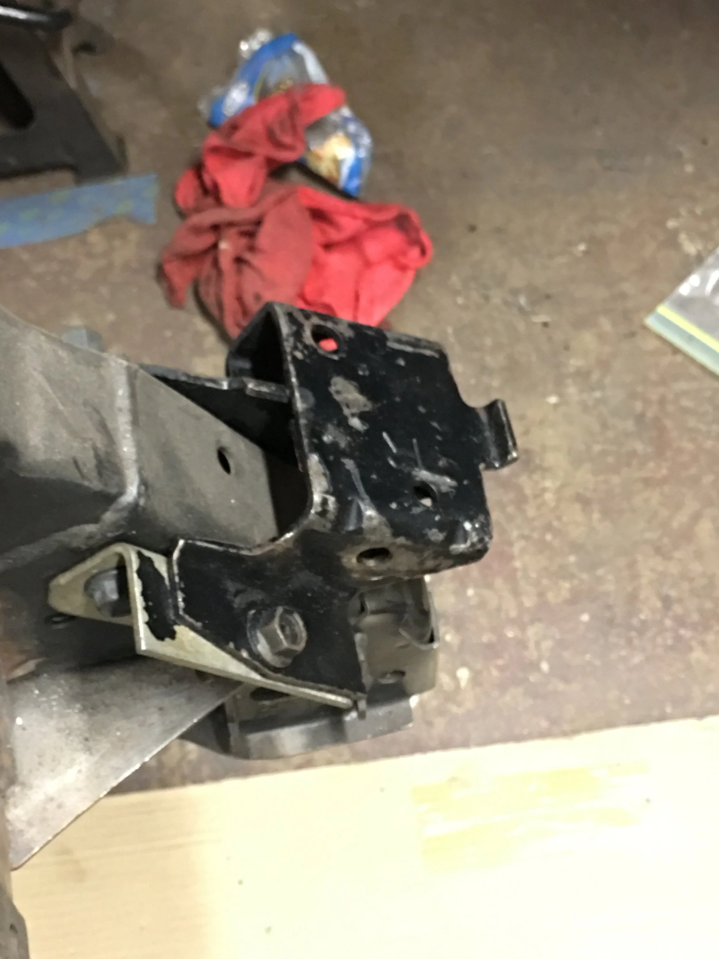
The engine mount brackets for the frame go on cleanly. That’s a relief. The engine plates should bolt up just as easily.
I have to quit kidding myself like this.
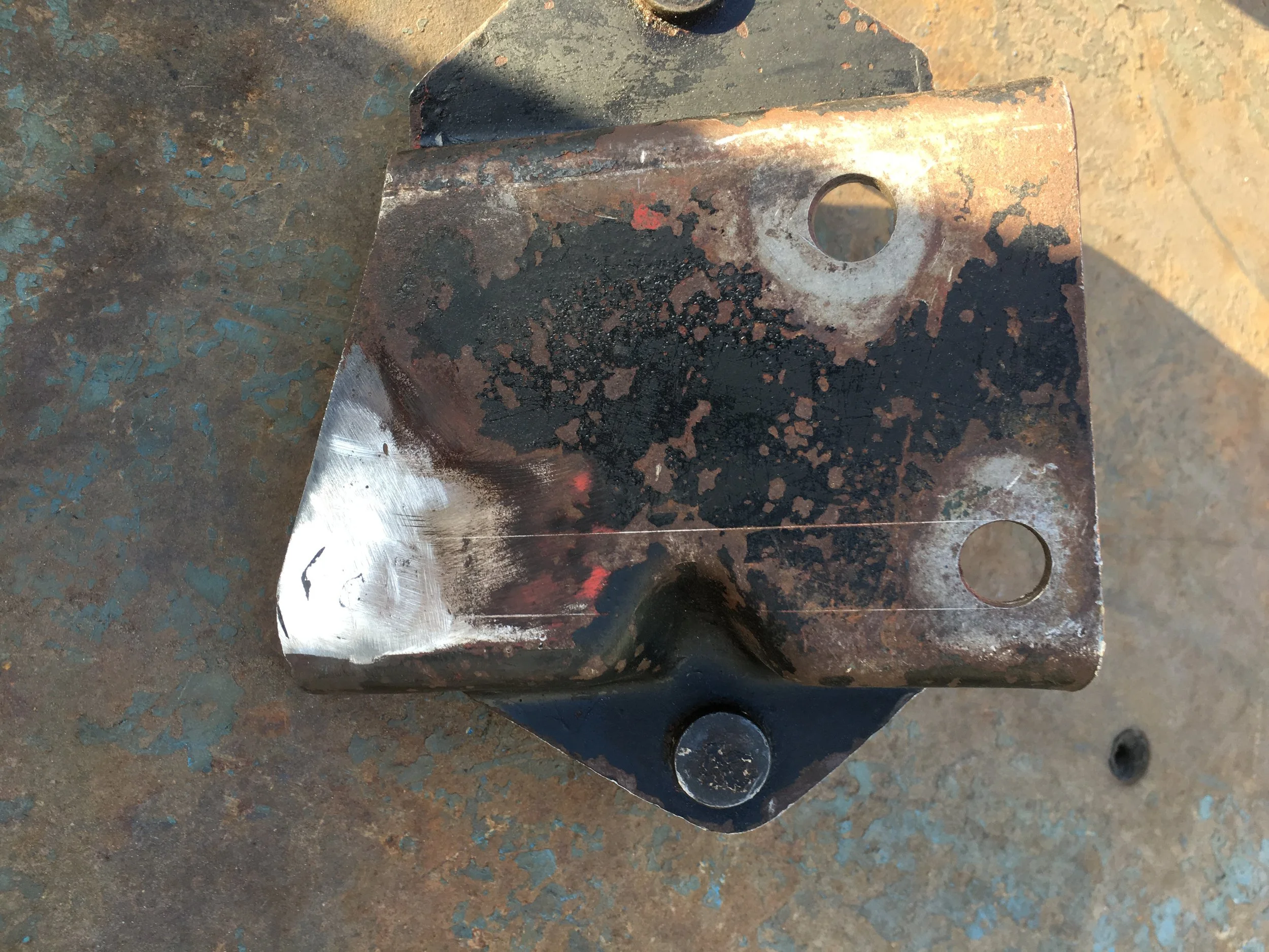
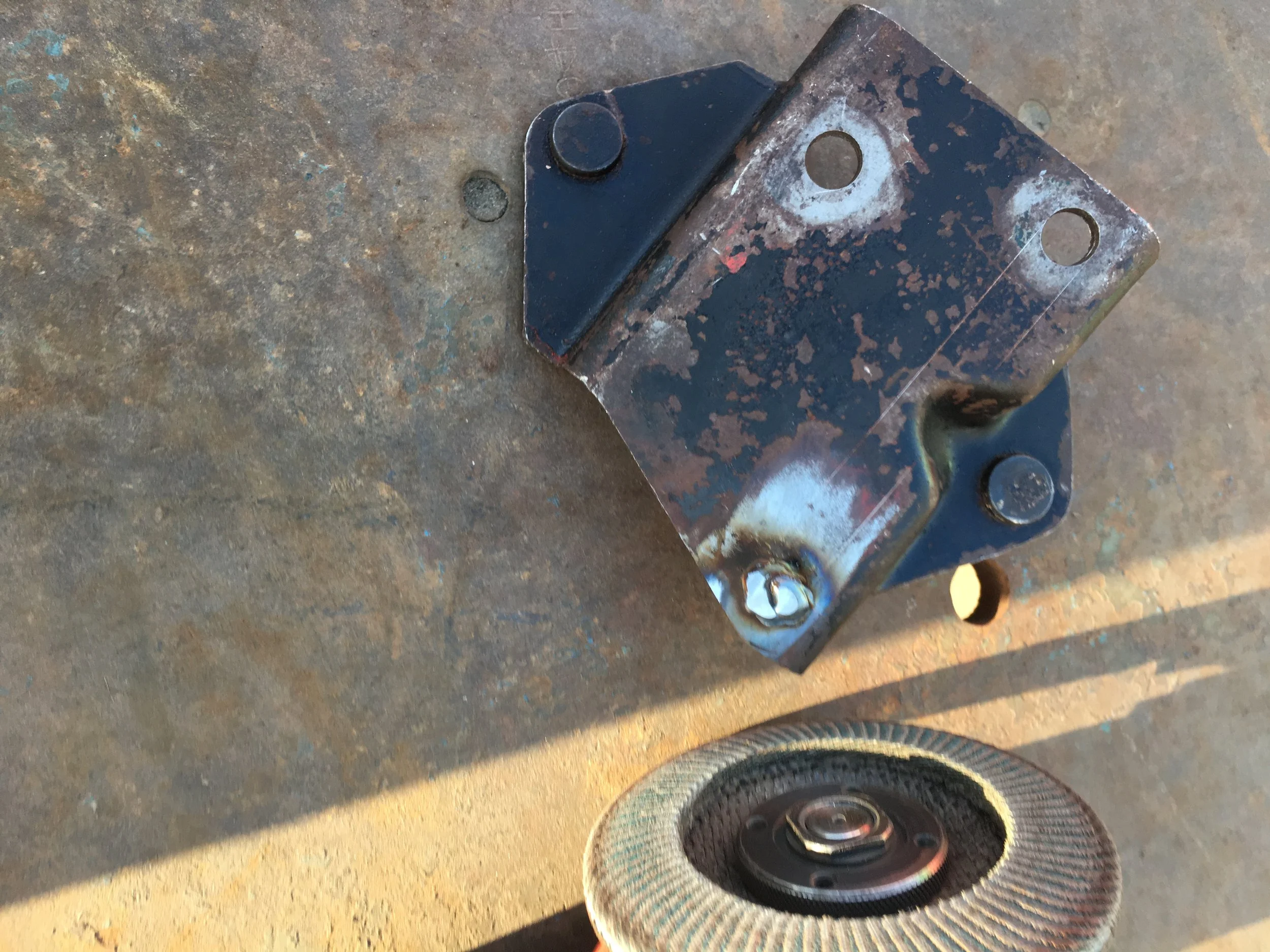
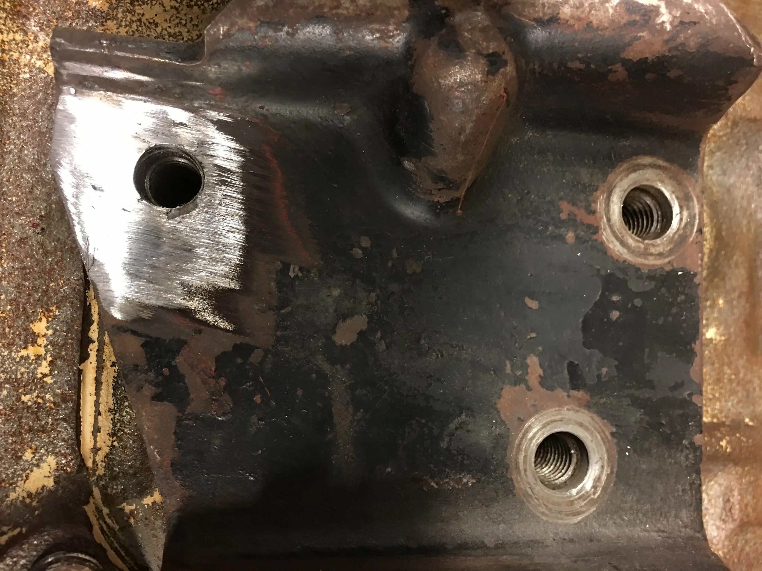
The 427 was unique in the FE series. The early versions had an oiling system that used priority oiling to the top of the engine; lifters, camshaft, etc. The crank was oiled after that. This is how just about all of the different FE engines were oiled. Ford revised the oiling on the 427 in 1965. The 65 427 had crankshaft priority oiling and it did just that, the oil was directed to the crankshaft main journals before being routed to the cam tunnel. The early version block were known as top oiler and the later 65’ design was called the side-oiler. The SOHC used the side oiler block. Why am I rambling on about this? The side oiling system changed the external shape of the block. There was now a hump that ran along the side of the block, a hump that required one of the engine plate mounting bolt holes to be relocated upwards. Since the Mustang never came with a side oiler, no engine plates exist for it. Not earth shattering, just a little more work.
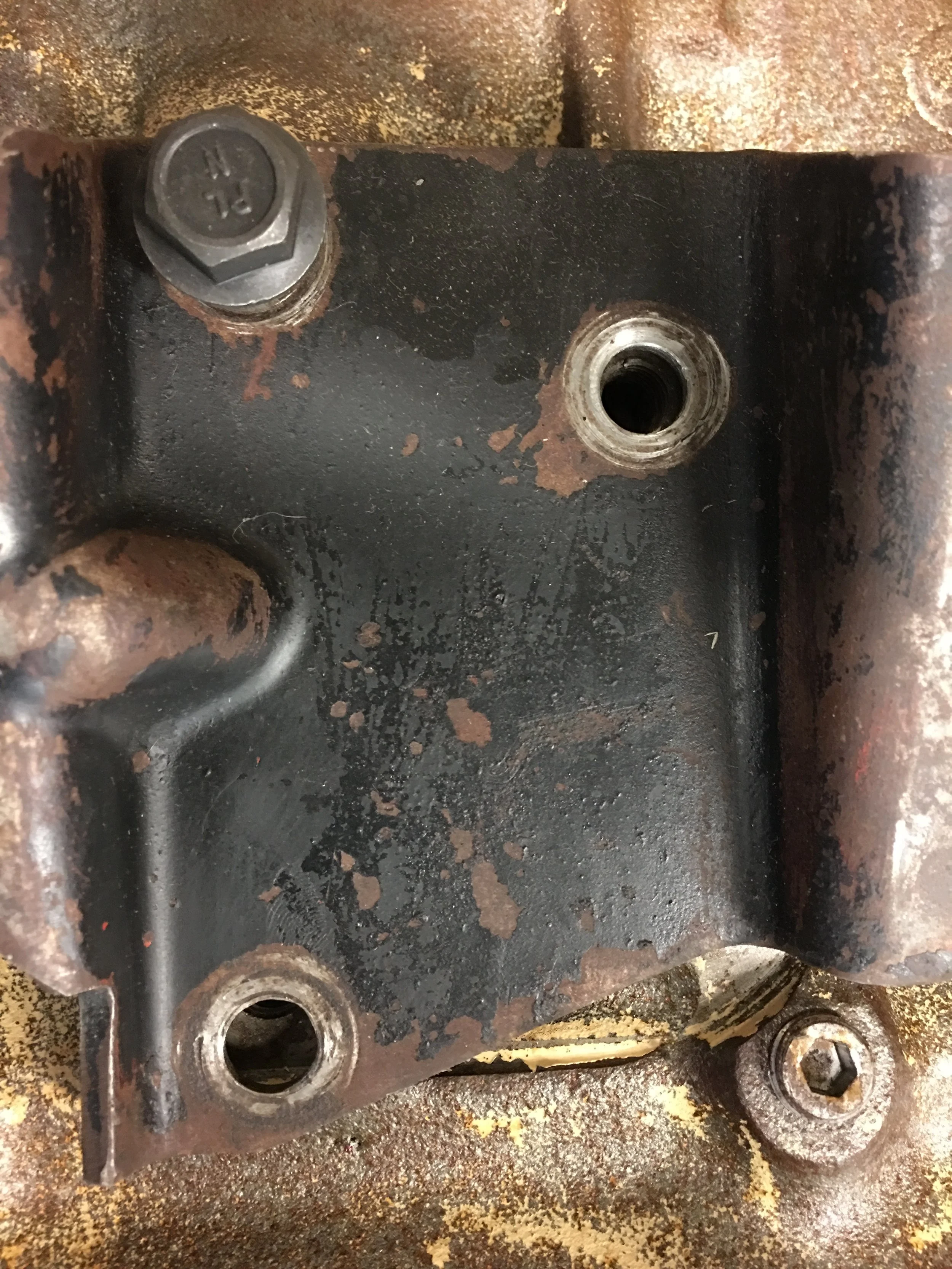
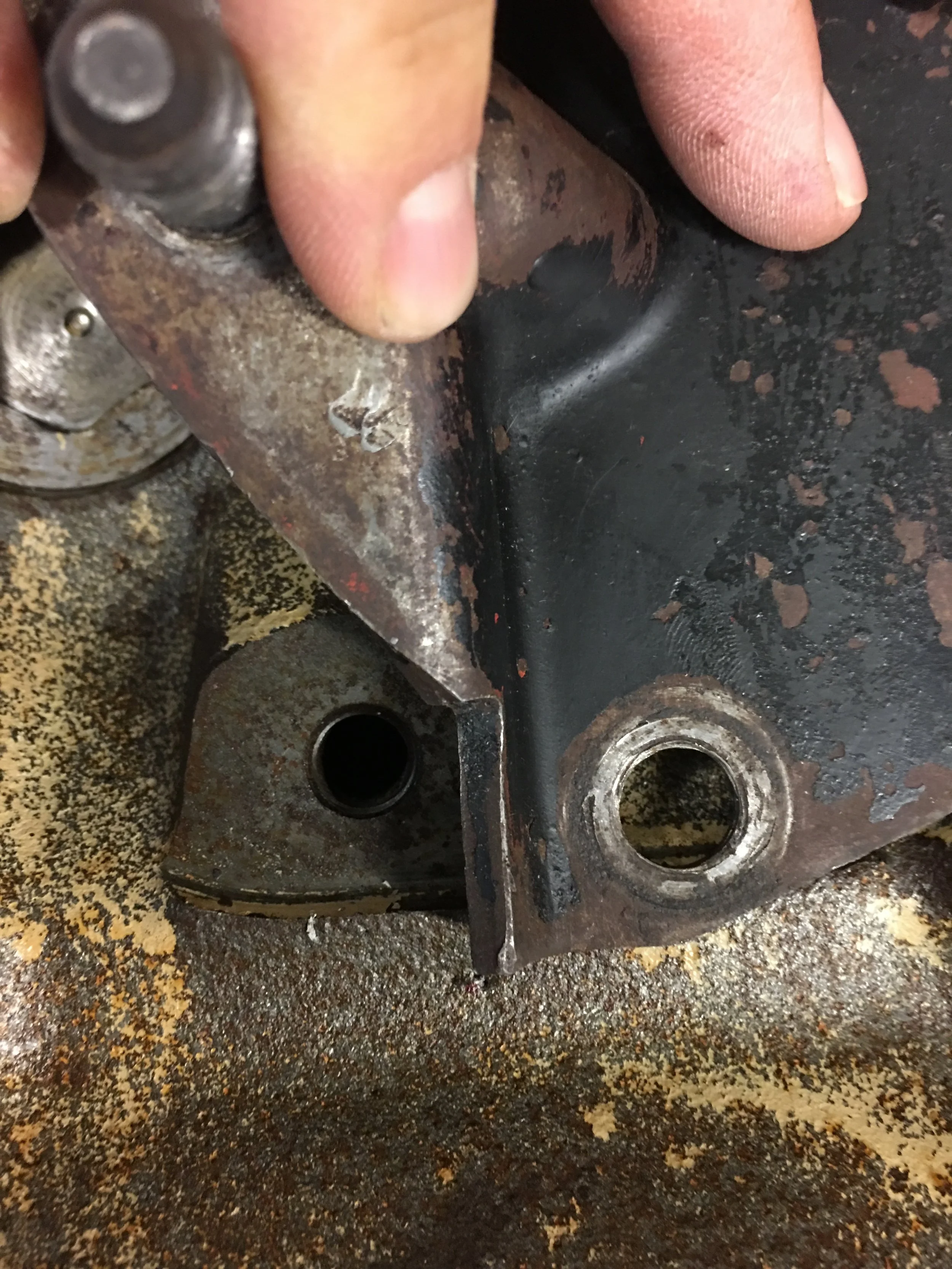
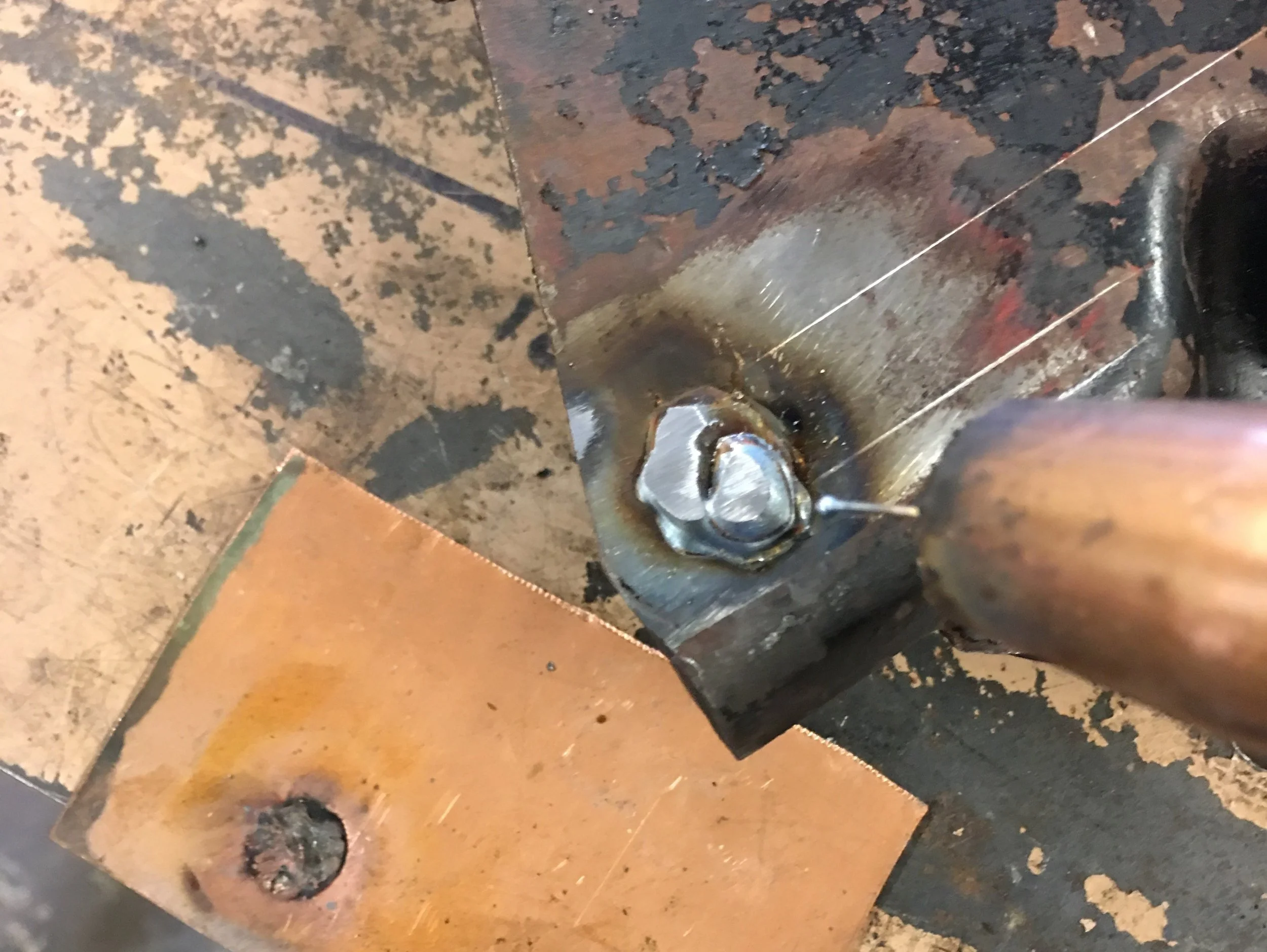
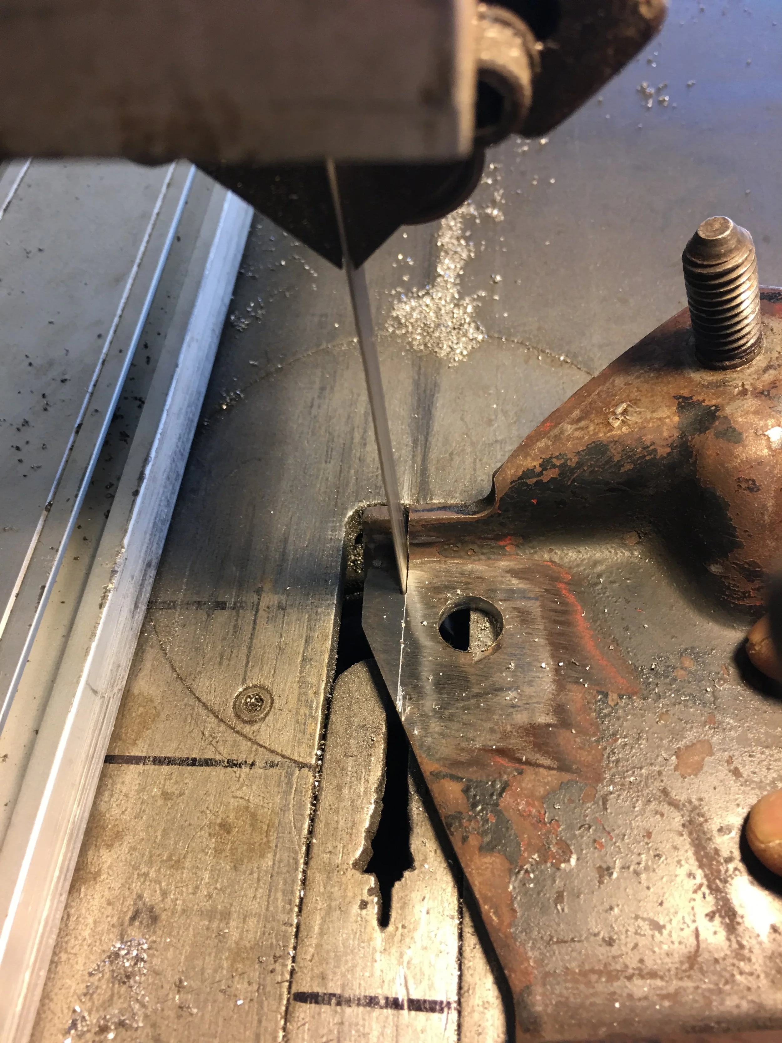
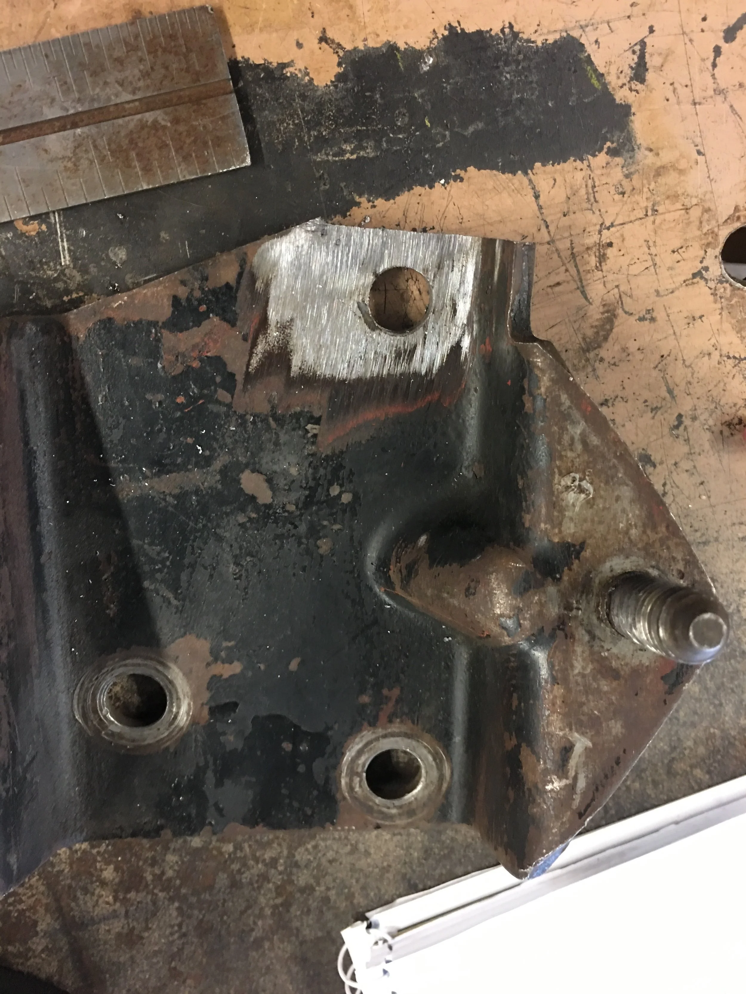
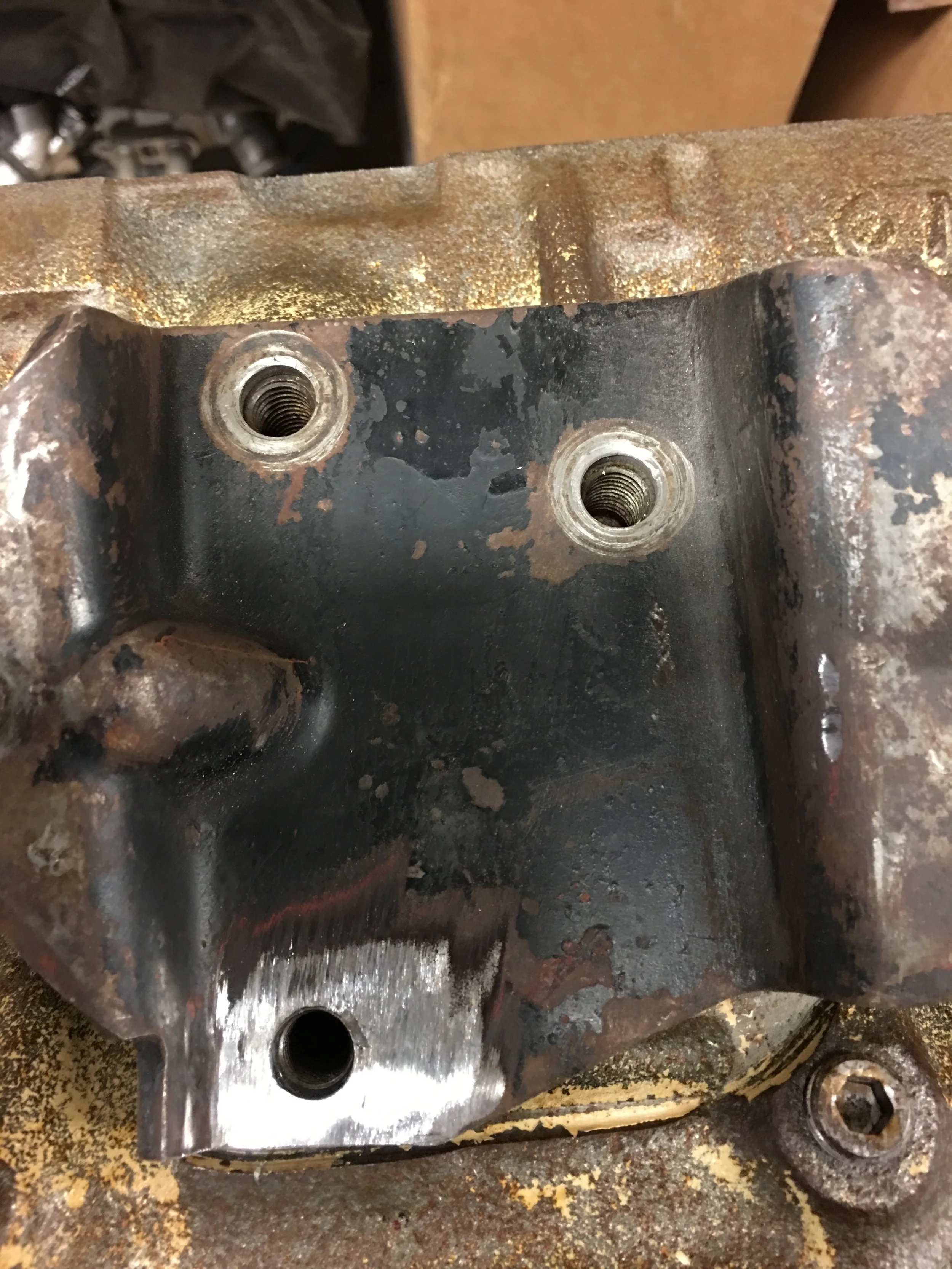
To begin the engine plate modification, I decided to fill the hole that would be redrilled higher up. I’ve seen example where the plate was trimmed and then the hole was augered out to line up with the displaced mounting hole on the block. That’s ugly. This hole was welded shut using the Mig and then ground flush. The new hole was drilled and the plate was cut to fit.
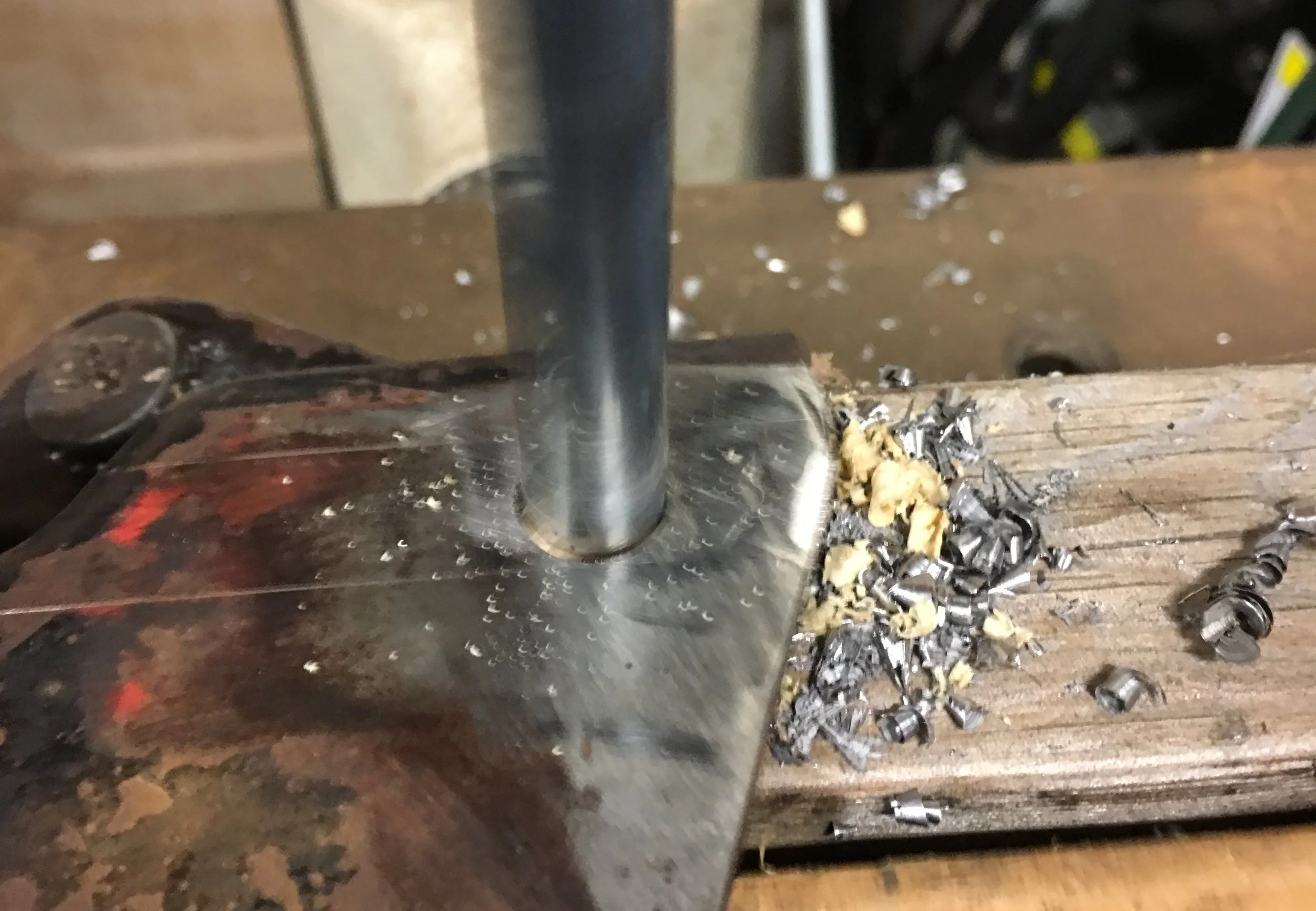
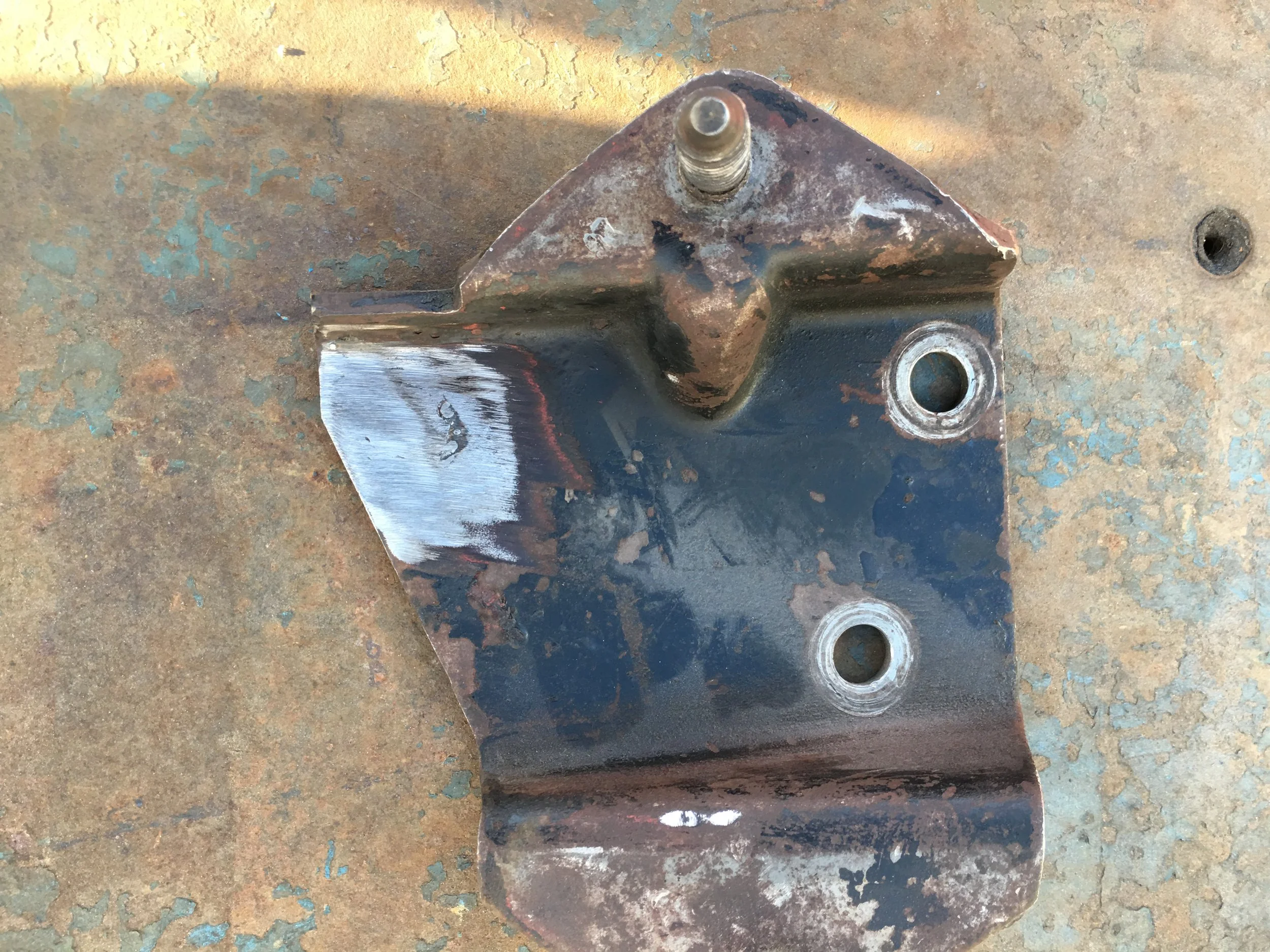
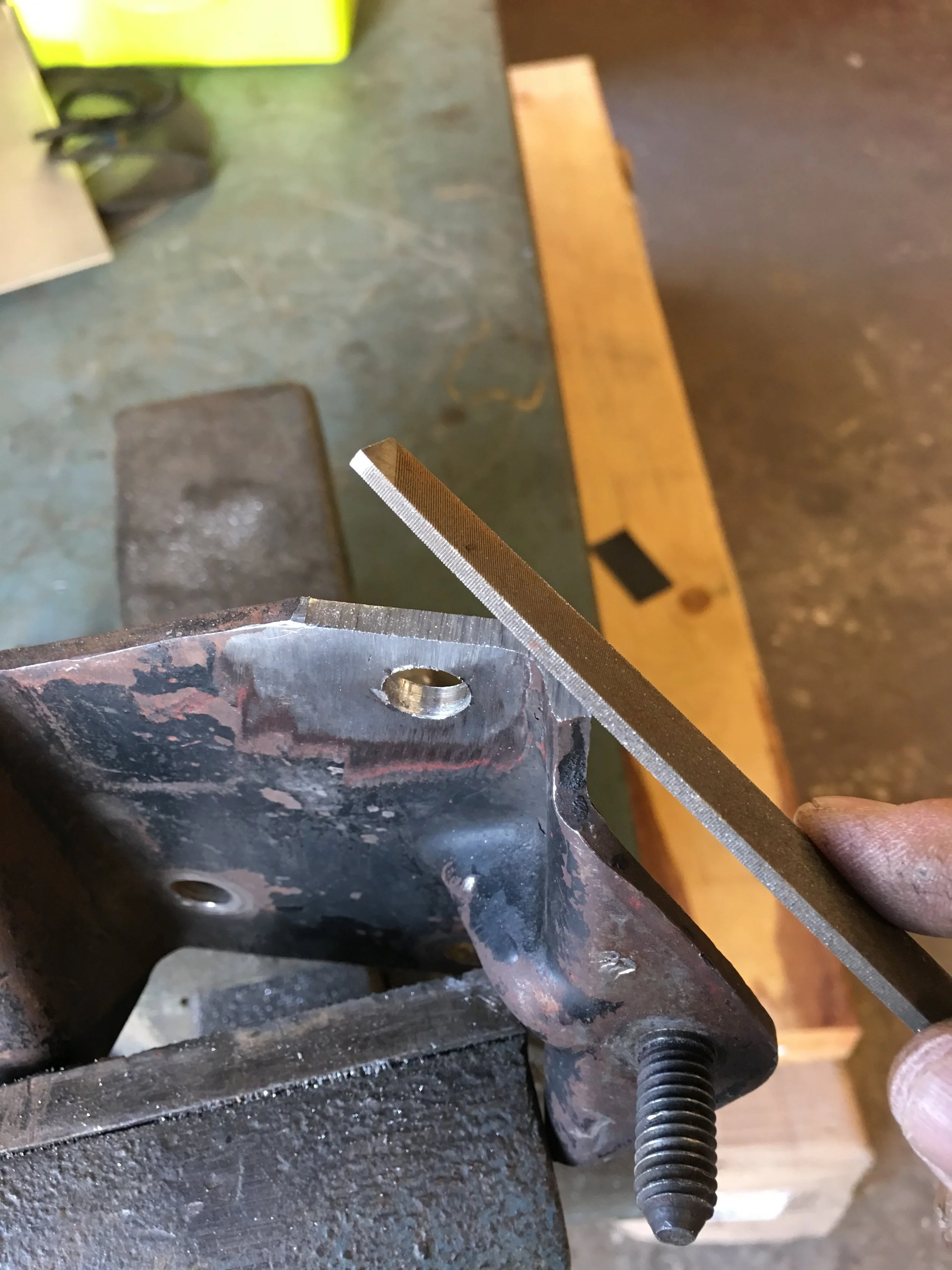
That job took very little time but the next step wouldn’t go quite as easily.
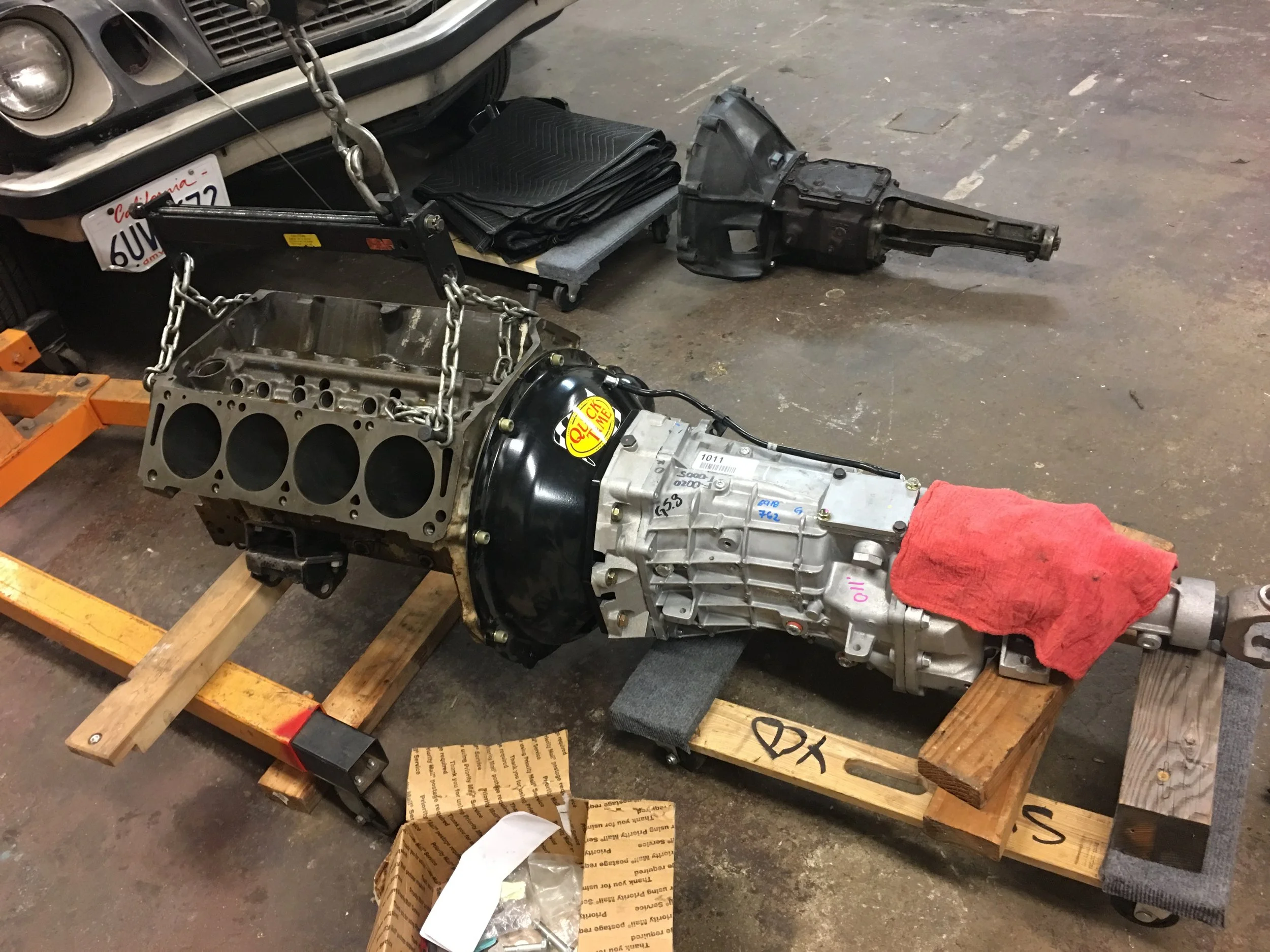
With the plates and mounts bolted on, the rubber isolators were bolted to the engine plates. By this time I had saved enough money, it had been 5 years since the engine purchase and 3 from the car purchase. to buy the transmission and bellhousing. I picked up a Tremec T56 Magnum and a Quicktime engine adapter/bellhousing. These were bolted to the bare block and the combination was lowered into the Mustang.
The engine mount bolts don’t go through.
I’ve fought with these engine bolts before, not Ford specifically but the through bolt design and I’ve never failed to coax the bolt through, whether by screwing it in or hammering it through. This thing won’t play. either side. I’m starting to worry that my fear is founded and the shock towers are screwed up.
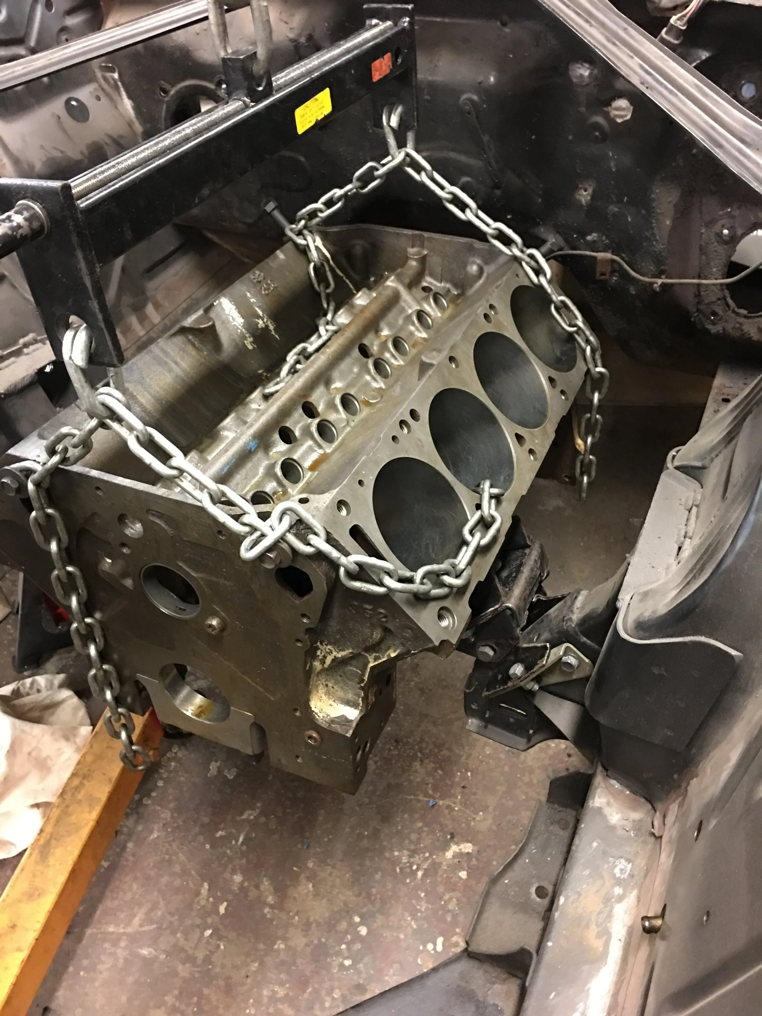
To get back to a basic view , the engine and tranny get pulled out and I separate the block and try dropping that in by itself. The bolts slide through after a little jiggling with a crowbar between the frame mount and the engine isolator. Ok, this is good. I have hope for these towers.
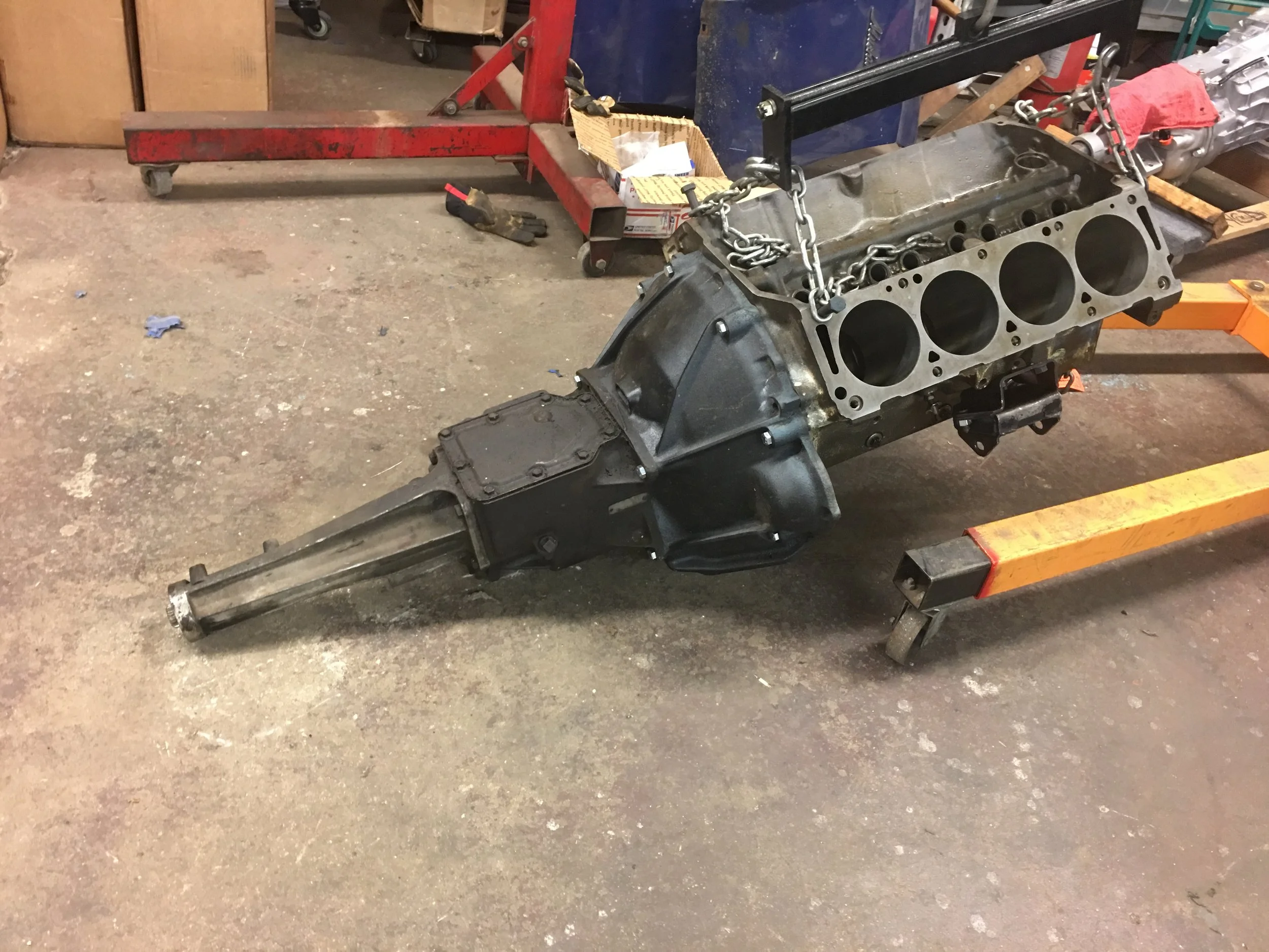
Next test. I have a bellhousing to mount a top loader to an FE block. I dig through my pile of piles and drag the bellhousing out. I have a replacement top loader and I bolt them to the block and lower the assembly into the car. Once again the bolts slide through.
I don’t get it. Two out of three combinations work but not the most important one.
I have to try the 6-speed one more time. Still can’t get the bolts to pass all of the way through. they only go part way and that’s when I notice that the ends of the isolator do not line up front front to back, it’s like they’re twisted. I pull the assembly out again and set it on the shop floor.
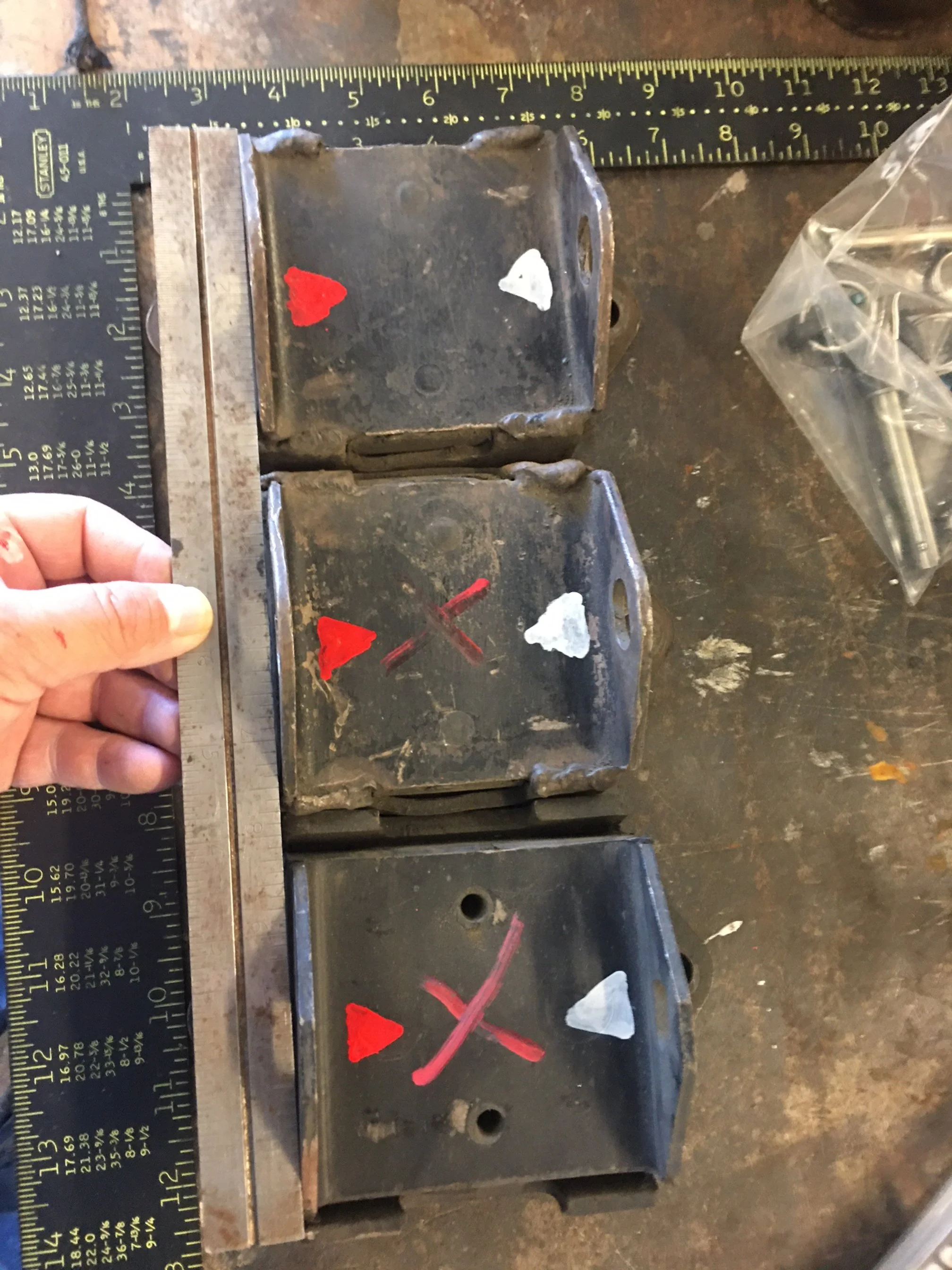
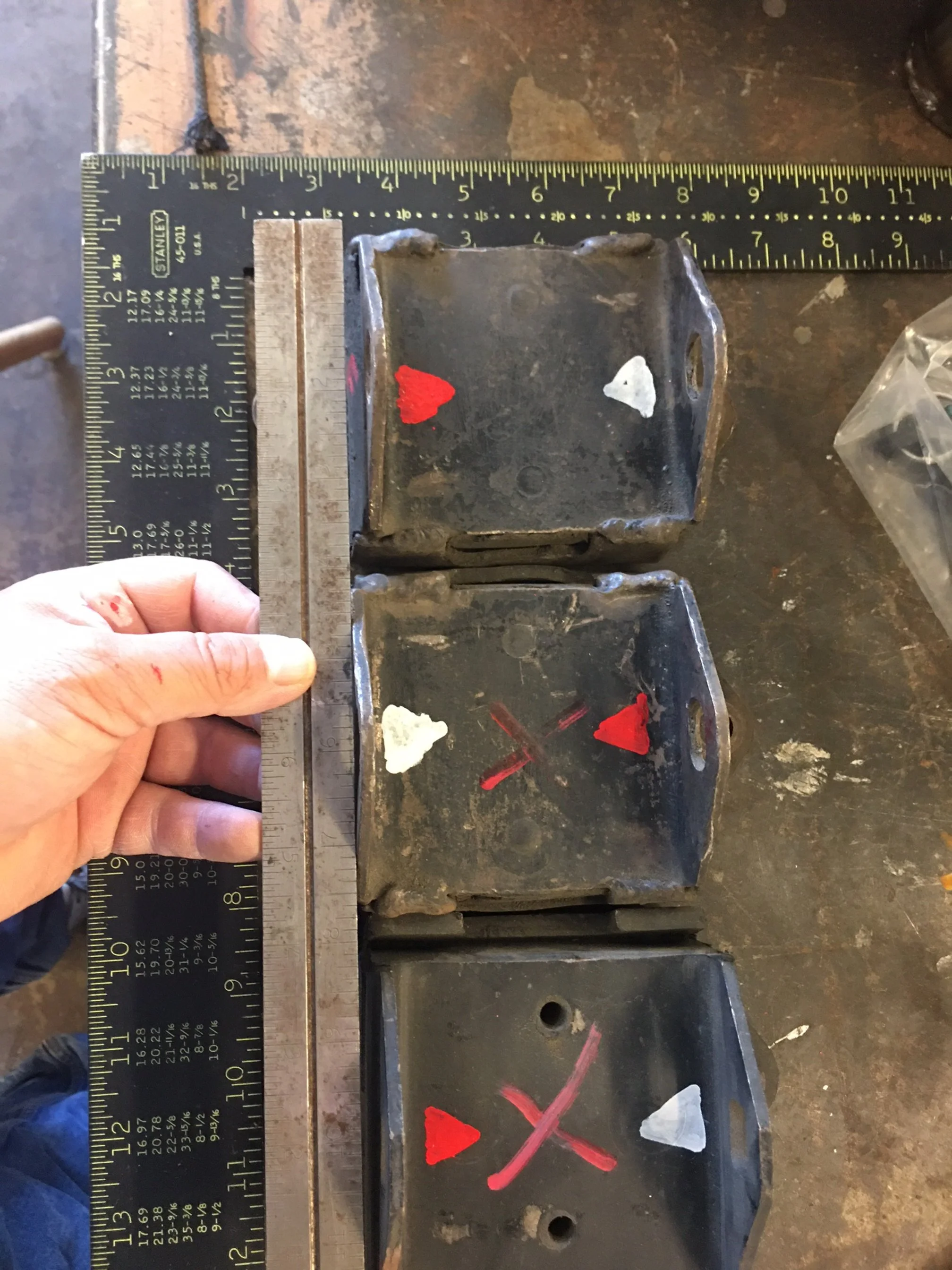
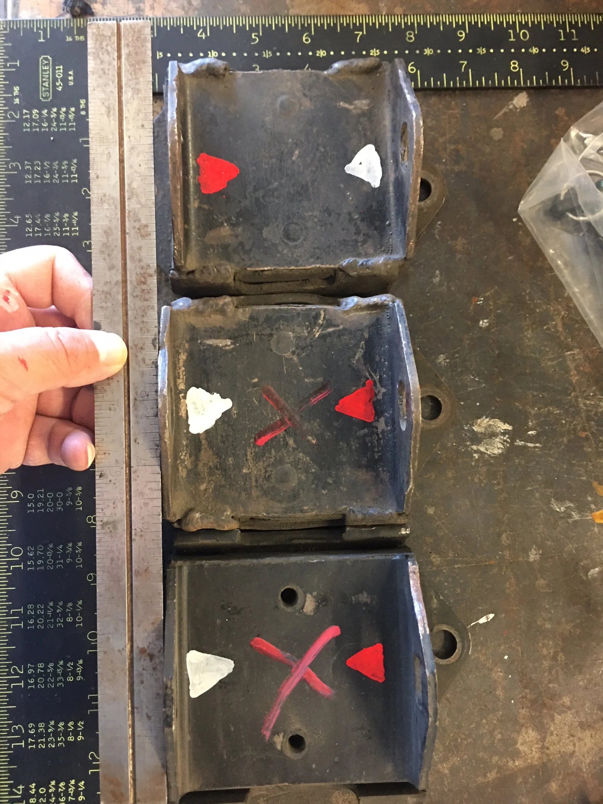
I unbolt the block again and stare at it. I’ll intimidate it into working. I measure from the back of the engine to the studs on the engine plate that the isolators bolt to. They’re the same from side to side.
What I found out, in my case anyway, is that even though the isolators look identical and can be mixed and matched in any direction, there is actually a 3/16” of an offset between the mount/isolators depending on how you have them lined up. The set that came with the kit from ebay had been welded to create a solid engine mount. Maybe they welded the isolators wrong. I bought a new set. These also had the 1/8 to 3/16 offset. I spin one mount in relation to the other until all mounting holes are flush. I’ll take as much rearward offset as I can get so I mark the mounts “front” and “back” so as not to get them mixed up again and bolt them to the engine. Transmission gets bolted back up to the block and lets try it again.
The engine drops in and the bolts finally slide through. Holy Shit! They don’t slide in silky smooth. I do have to use a screw driver to get the holes to line up but the bolts will go all of the way through.

Because I like the pain, I pull the engine back out and spin one of the mounts around and drop the drivetrain back in. The mounts don’t line up. Good, that would have made me blow a gasket had it dropped in. I normal everything and the engine drops back in. I take advantage of this and get a laser that will sit square to the output shaft of the transmission. Elevation is off but the rear end pinion center lines up pretty damn close with the transmission output shaft. I feel confident that the shock towers are sitting where they’re supposed to.